Fabrikator Mini
My modifications for the TinyBoy Fabrikator Mini
Project published on March 01, 2016.Last updated on January 27, 2022.
...back to 3D Printing overview
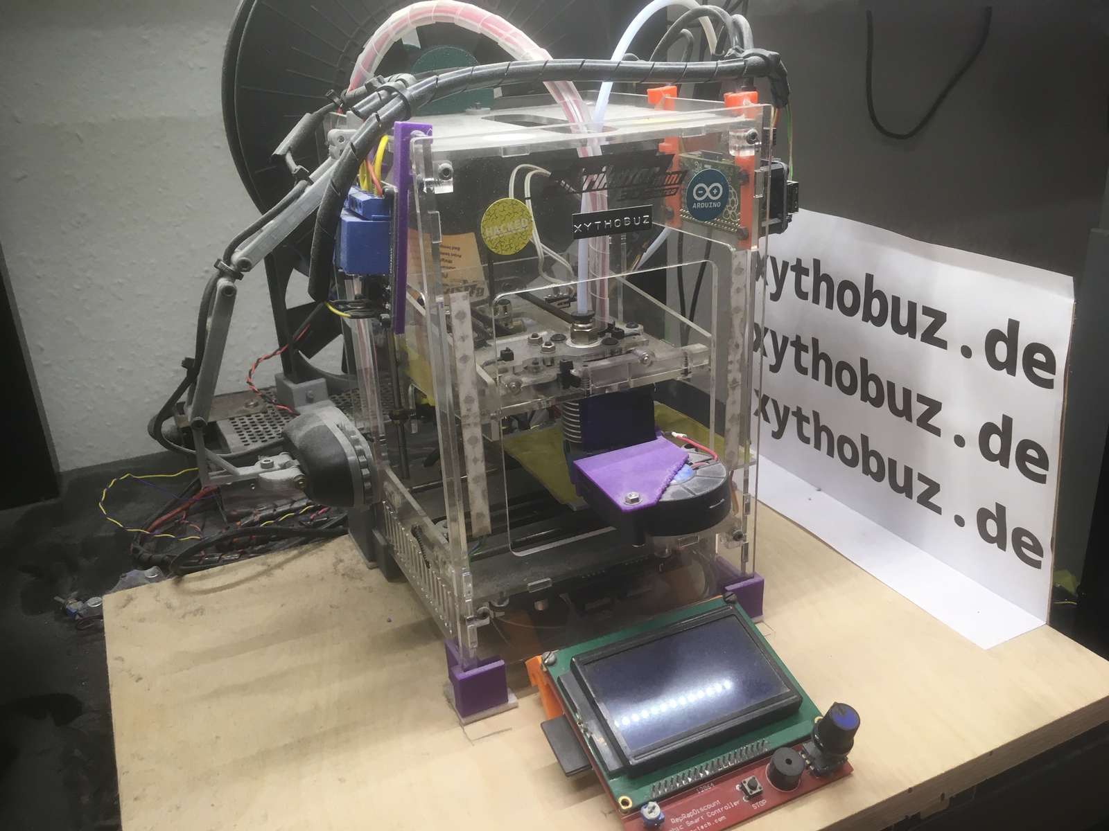
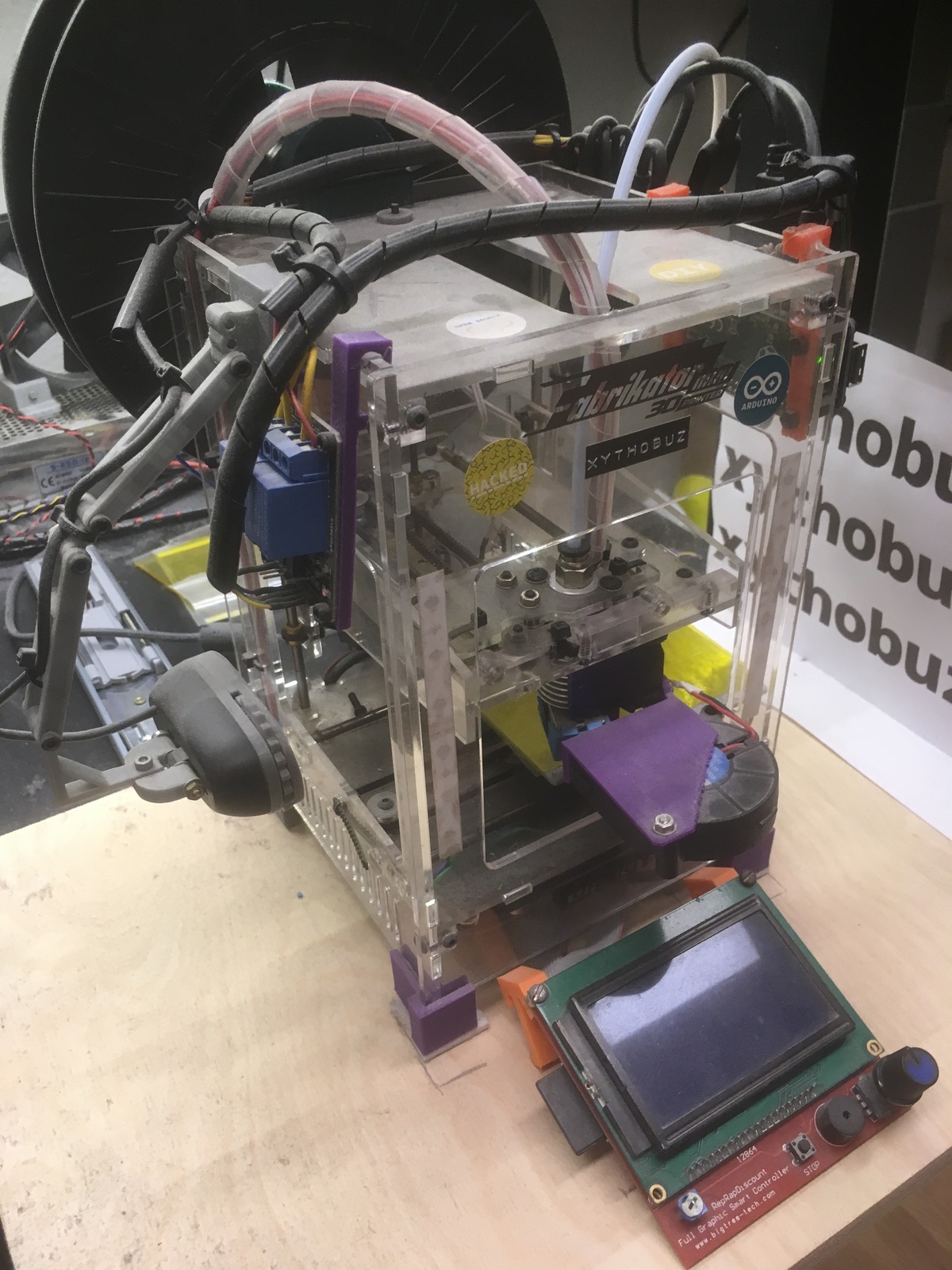
I bought the Fabrikator Mini V1.5 from HobbyKing in March of 2016. So that's pretty much exactly three and a half years ago, at the time of this writing. I'm unbelievably happy with this printer and how it held up over the years.
So first, some background. It is a clone of the educational TinyBoy printer, the frame entirely made from acrylic sheets, with a print area of only 80x80x80mm. As a result, only very slow print speeds of about 20mm/s are feasible. I guess that's one of the reasons it delivers such surprisingly good print results.
Of course, as with every printer, there were some rough spots and problems, but with a bunch of modifications and different parts this machine is now firmly holding this place as my go-to workhorse printer.
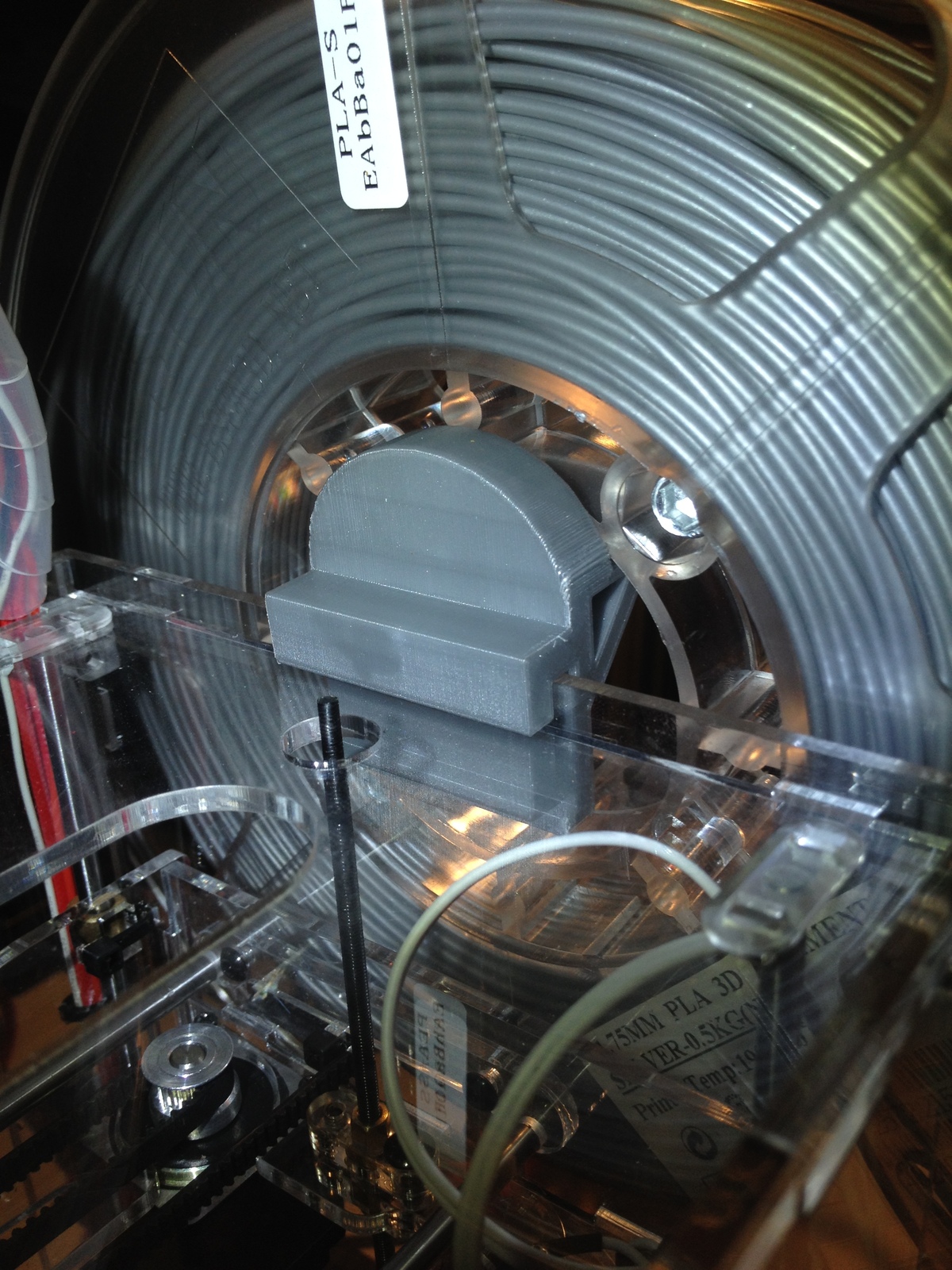
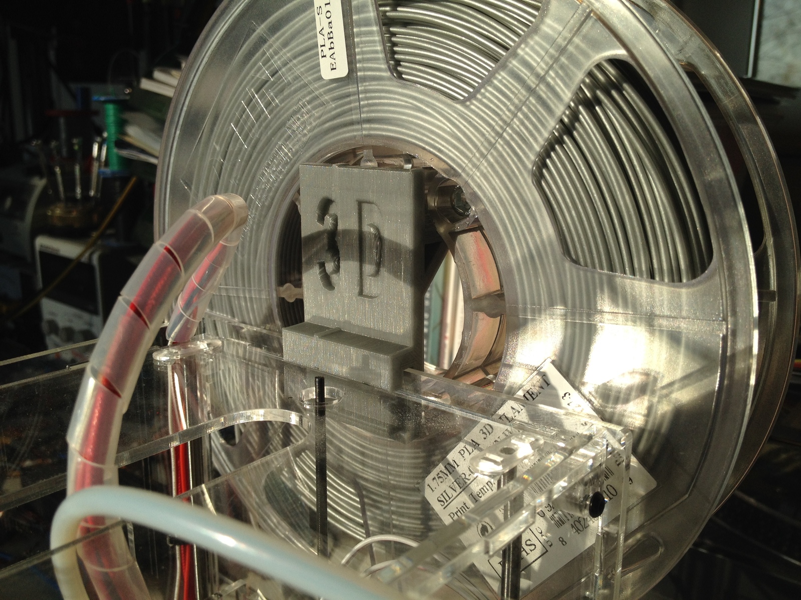
Spool mount
One of the first problems I ran into was mounting the filament spool. I found a ready-made solution on Thingiverse, which I was using for a while, until I switched to a different brand whose spool did no longer fit. Because of that, I designed my own holder.
Feet
With a heavy filament spool mounted on the backside of the printer, it was no longer standing upright. Because of that, bigger feet were needed. Luckily, there was also something available already. I just had to cut a bit off in OpenSCAD to get matching front feet.
TODO photos
Power Supply Replacement
I did not really trust the stock power supply and I also needed more power available for further modifications. So one of the first steps was replacing the power supply. I did opt for one of the generic large chinese 12V supplies offered on eBay, I chose the 20A version. To make it at least a bit safer, I cut, bent and screwed a piece of brass sheet over the 220V input terminals and added a power-button. On the output side I did keep the old connector from the stock power supply. I also added a 12V indicator LED I still had lying around. In my configuration, the power supply is always turned on, powering the Raspberry Pi that controls the printer power via a relay board. See below.
TODO photos
Heatbed Replacement
One of the first problems I ran into were with the printing surface.
In its stock configuration, the Fabrikator Mini has an acrylic sheet with blue painters masking tape on top as its print surface.
This works, but I was not entirely happy with the adhesion of PLA and the need to frequently replace the tape or even use stuff like glue or hairspray to keep the prints firmly in place.
So I did a search on eBay, and found a vendor offering replacement aluminum heatbeds specifically for the Fabrikator Mini. They were made tinyfab.xyz, they now have their own webshop listing the heatbed. Unfortunately, it no longer seems to be available.
I've also bought a 80mm wide kapton tape roll and have been using this as a print surface on the aluminum heatbed ever since, only replacing it when needed after I damaged it on print removal.
Depending on how you solder the power supply wires to the heatbed, it can either run in a 15W or a 60W configuration.
I found the 15W setting to be painfully slow in reaching usable temperatures, so I have been using the 60W variant basically from the beginning.
Of course, as mentioned before, I used a beefier power supply for this that can handle the load. I did not however replace the DC connector on the printer or use a MOSFET or anything special. Both the connector and the (in stock unused) heatbed MOSFET seem to be able to handle the load in my configuration, even for very long prints.
I did have some problems with properly routing the cables for the heatbed, a couple of times the cable broke where it flexed the most after many prints. I've drilled a bigger hole into the bottom acrylic plate, used flexible silicon cables, a bunch of cable-ties and gaffer tape on the heatbed underside and it now seems to hold up well.
TODO photos
Custom Firmware
Luckily the main board already has a MOSFET for the heated print bed that was unused in the original setup. But of course, to enable support for the heatbed, I had to compile my own custom Marlin firmware. This is also recommended for safety reasons, as the chinese manufacturers often leave out the temperature runaway shutoff in their firmware config.
I also wrote this blog post about my Marlin modifications.
Mesh Bed Leveling
Even though it probably shouldn't be necessary for such a small printbed, I did still have some first layer adhesion issues with the aluminum printbed. Especially one corner seems to be a bit bent. So I enabled Mesh Bed Leveling in my Marlin Firwmare (see below) and also wrote a little GUI Tool to assist the leveling process. It is also on GitHub.
Here is my latest measured mesh, for example. Also be aware that these values differ significantly between a hot and a cold bed, so always do the leveling on a fully heated bed!
       0        1        2        3
0 -0.12500 -0.07500 -0.10000 -0.10000
1 -0.12500 -0.10000 -0.12500 -0.10000
2 -0.07500 -0.12500 -0.12500 -0.10000
3 -0.10000 -0.12500 -0.12500 -0.15000
And this is really just an example! Do not just copy these values to your printer, they will differ of course.
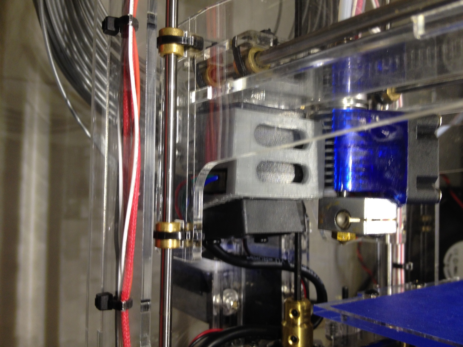
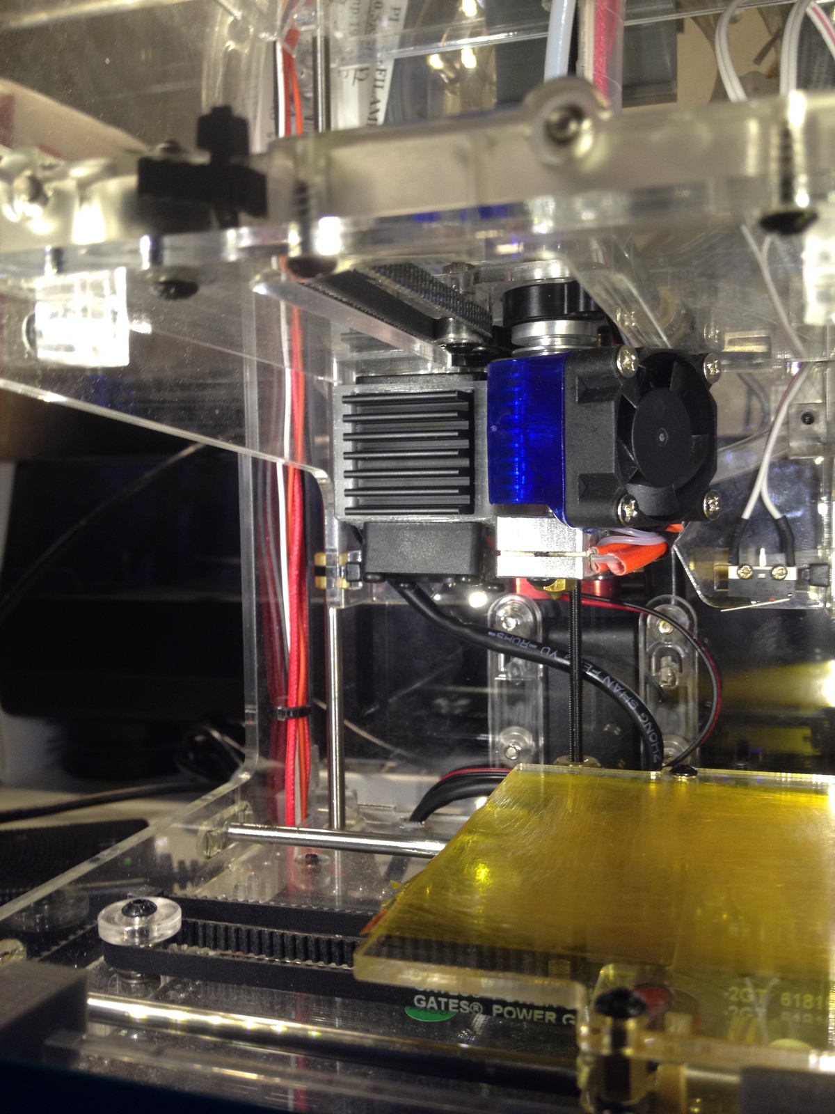
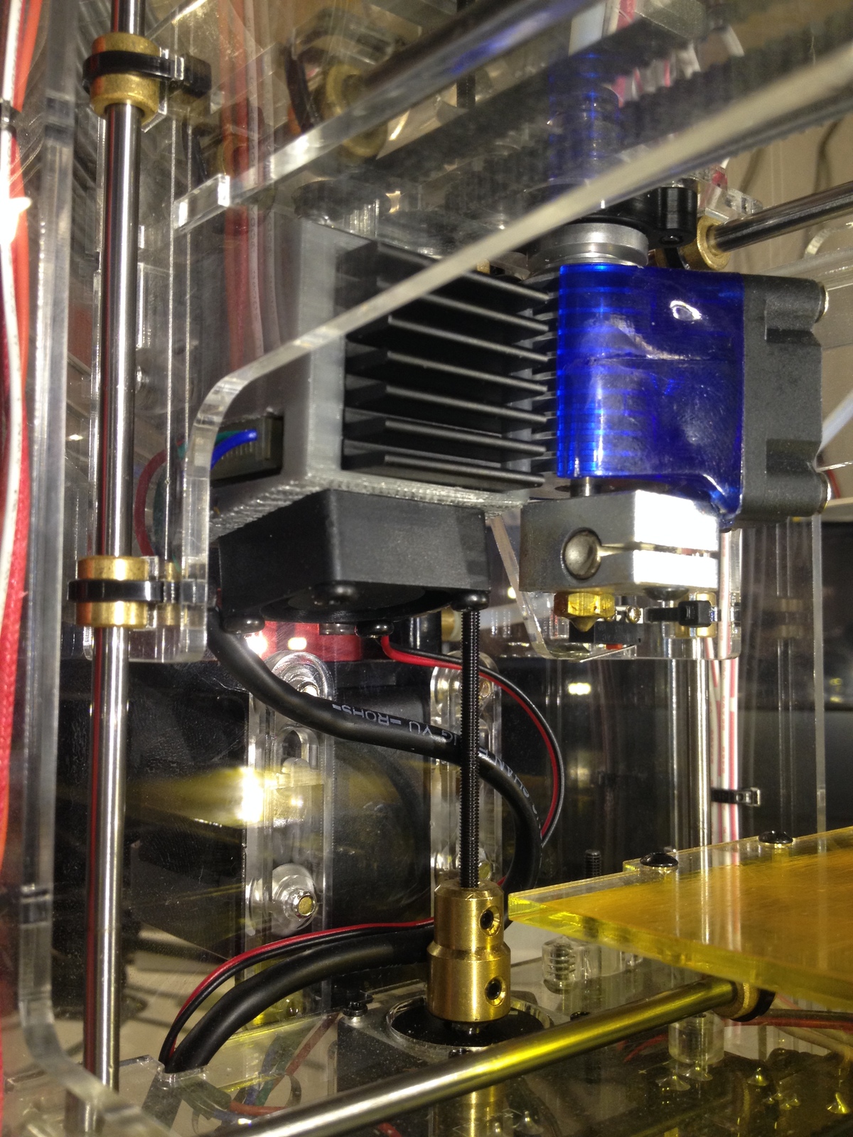
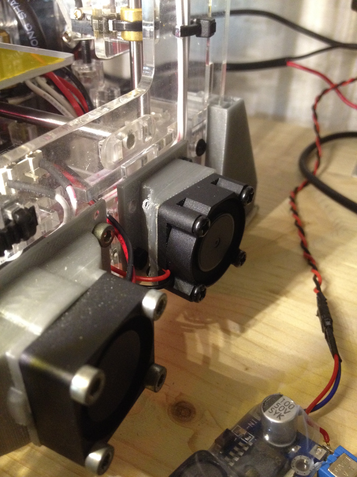
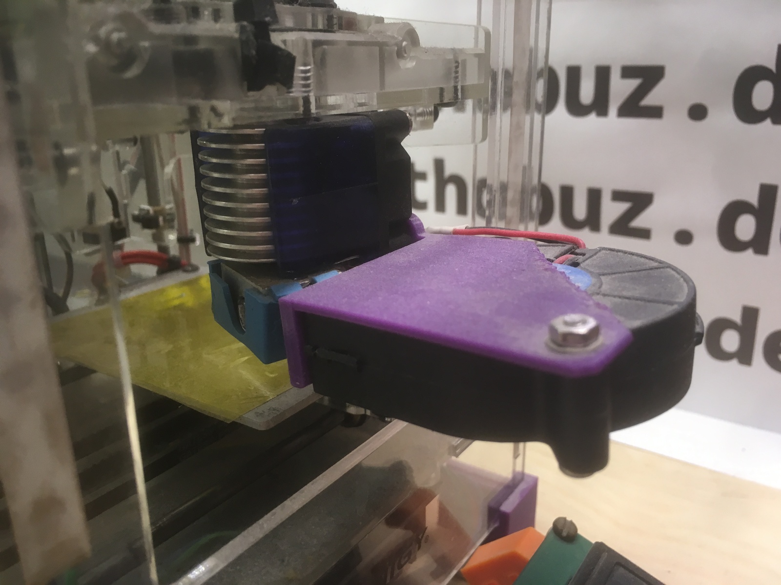
Temperature Issues
With all of this added load, and even in its stock configuration, the Fabrikator Mini electronics and stepper motors run very hot. So hot that I did not feel comfortable leaving it like this. So I've downloaded and designed small fan-mounts for the X and YZ stepper motors and added small heatsinks to each motor and to the extruder stepper. Of course, I also tried reducing the stepper motor reference voltages first, to run the motors with less current, but even on the lowest setting without skipped steps I still felt the motors and drivers were too hot. With all of these changes, the printer is now definitely louder than before, but it also runs noticeably cooler. I've wired all the additional fans in parallel with the stock hotend-cooling fan, so they turn on above 50 degrees Celsius in the stock firmware as well as my self-configured Marlin. Here are the link to the fan mount designs:
Z-Axis Noise and Wobble
Right from the start I noticed a very painful high-pitched squealing noise coming from the Z-axis whenever it moved. Even with lubrication I was not able to resolve this. But I noticed that it became unhearable as soon as I touched the tip of the axis that reaches out of the top acrylic plate. Of course, the axis has two fixpoints in the stock configuration, the motor at the bottom, and the nut in the z-carriage, and a mechanical system like this should not be fixed in position at the top as long as it is not perfectly aligned (which it isn't in reality, of course). So even though it's not advisable, and in theory should cause z-wobble in the printed parts, I did design a small insert for the top acrylic plate that aligns the z-axis to its center at the top. It is available on Thingiverse. It does in fact stop the noise, and fortunately I cannot notice or measure any z-wobble in the printed parts.
TODO photo
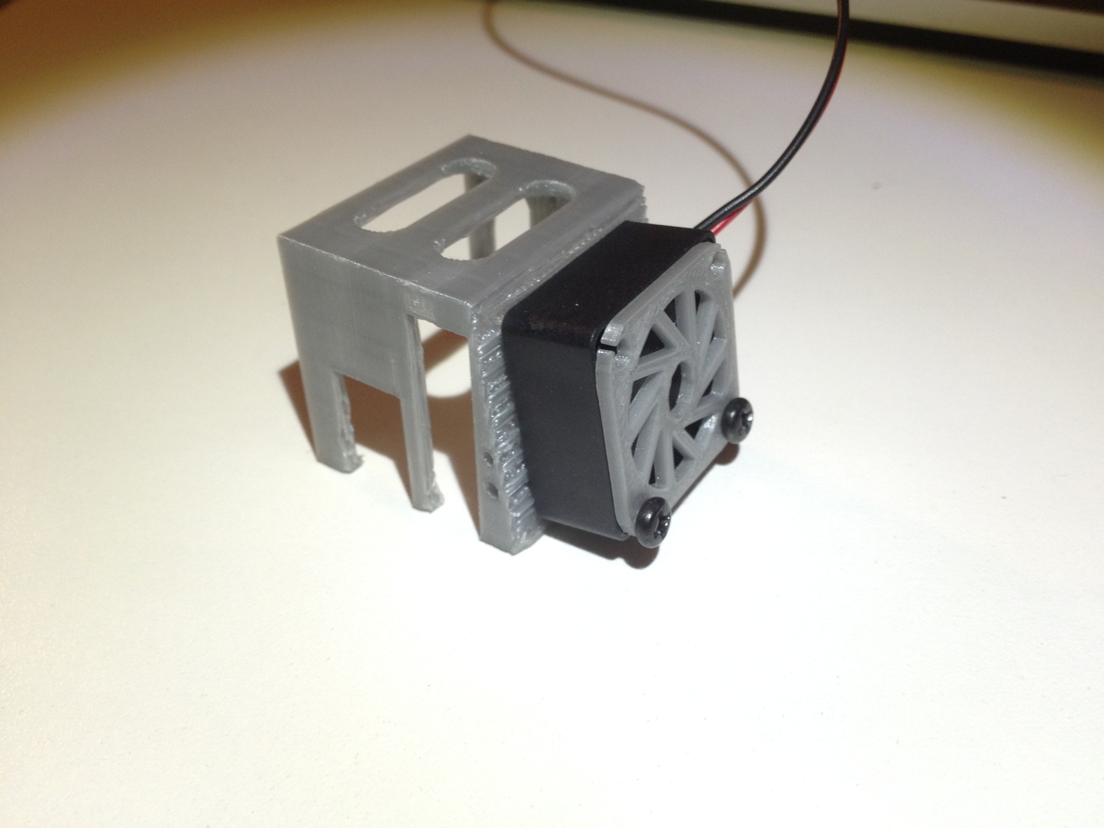
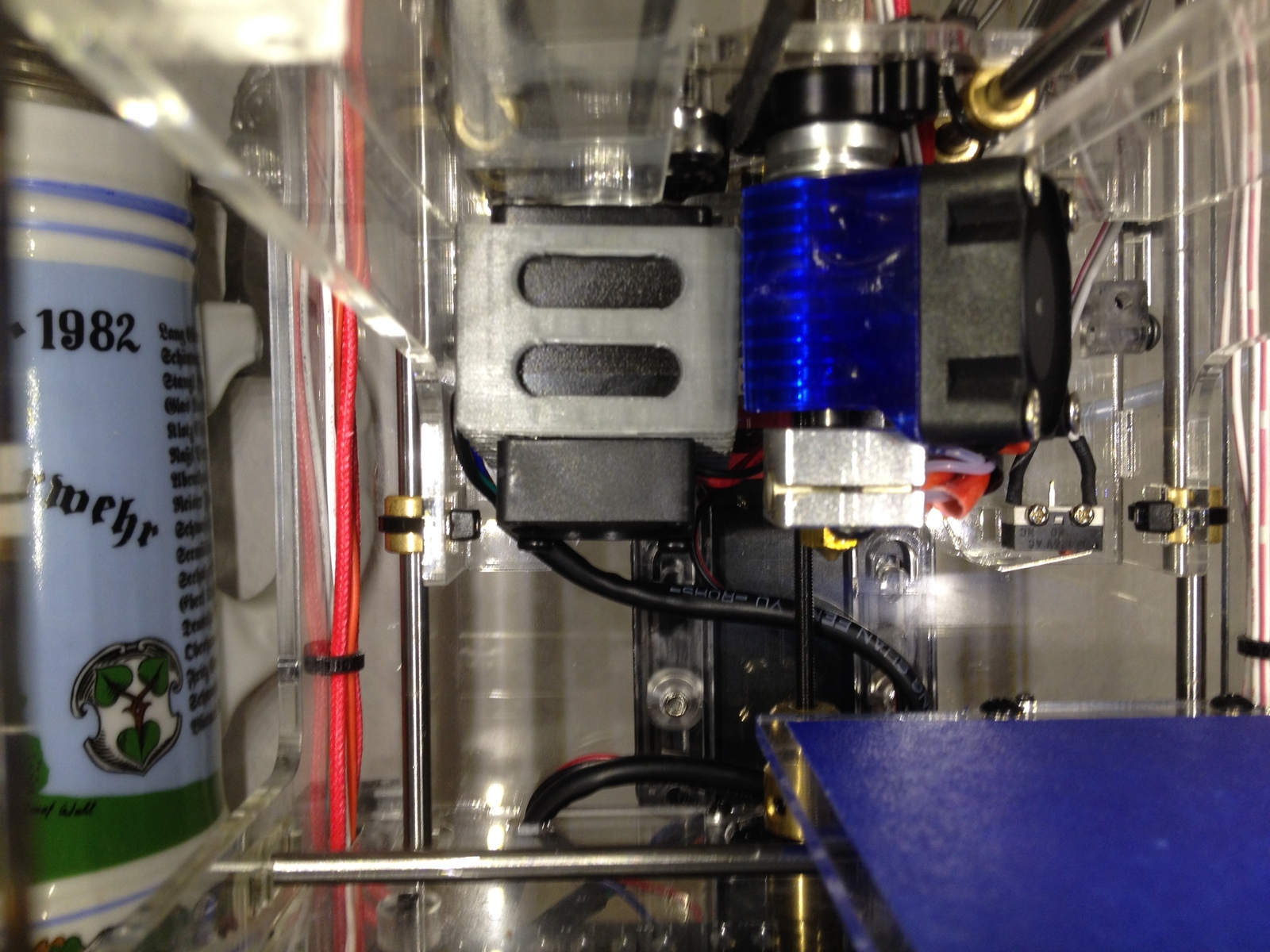
Part Cooling Fan
Even though print results were already pretty good, there was still some sagging noticeable on sections with long bridges, and also some stringing issues. Of course, the only real solution for these issues with PLA is a part cooling fan. As there is not a lot of room available, there aren't many options, especially if the part cooling fan should be independently controllable from the 3D printer controller. Fortunately, plasticmonk already designed a very good fan mount solution, allowing a standard 5015 radial fan to be mounted to the bottom two screws of the hotend fan.
TODO wiring hotend heatbed part-fan hotend-fan
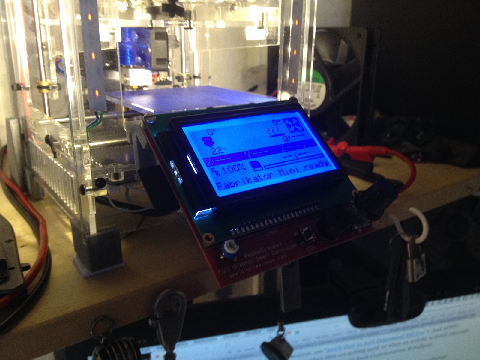
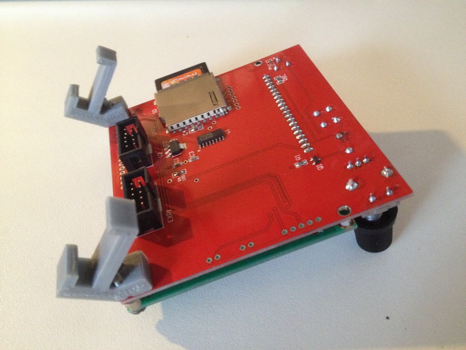
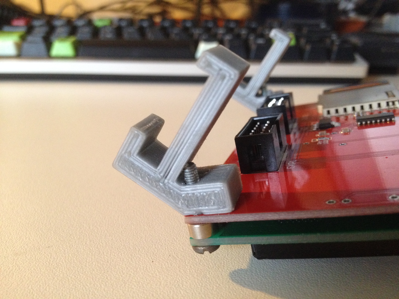
Full Graphics Smart LCD
To be able to properly control the printer and print from the SD Card (before I was using OctoPrint), it is very useful to install some kind of display for status informations and changing settings on-the-fly. One of the most common solutions out there is the Full Graphics Smart Controller that is available as cheap chinese clones easily. As there was no good mounting solution available that could also be printed with the Fabrikator Mini itself, I designed these small mounting brackets to hang the display from the front acrylic plate cutout of the machine. The controller board already has connectors available for the LCD. Just take care that the pinout matches, if I remember correctly I had to switch the connectors around.
Raspberry Pi Zero
Of course, to really properly utilize a 3D printer, you need OctoPrint! This is normally used in conjunction with a Raspberry Pi connected to the printer. It is not recommended to use low-powered Pis (below 2), but I decided to go with a Zero anyways. I had it lying around without a useful project and the formfactor matches the small Fabrikator Mini perfectly. As it is also printing very slowly, there's really not much load on the Pi itself, and I never had any problems printing from it. I do have to admit however, that the OctoPrint webinterface sometimes takes very long to load with this setup. But once it's there it works fine. I was even doing all my slicing for the Fabrikator Mini on the Pi Zero for a while.
To power the Pi, I'm using a small 5V step down converter that's connected to the 12V input of the printer. As the printer board is also connected to 12V and has its own 5V regulator, I decided to cut the +5V rail in the USB cable connecting the printer and the Pi. This way, the display backlight on my printer, as well as the mainboard, are turned off when the power supply relais is turned off. With an unmodified cable, the printer LEDs would be lit all the time the Pi is running.
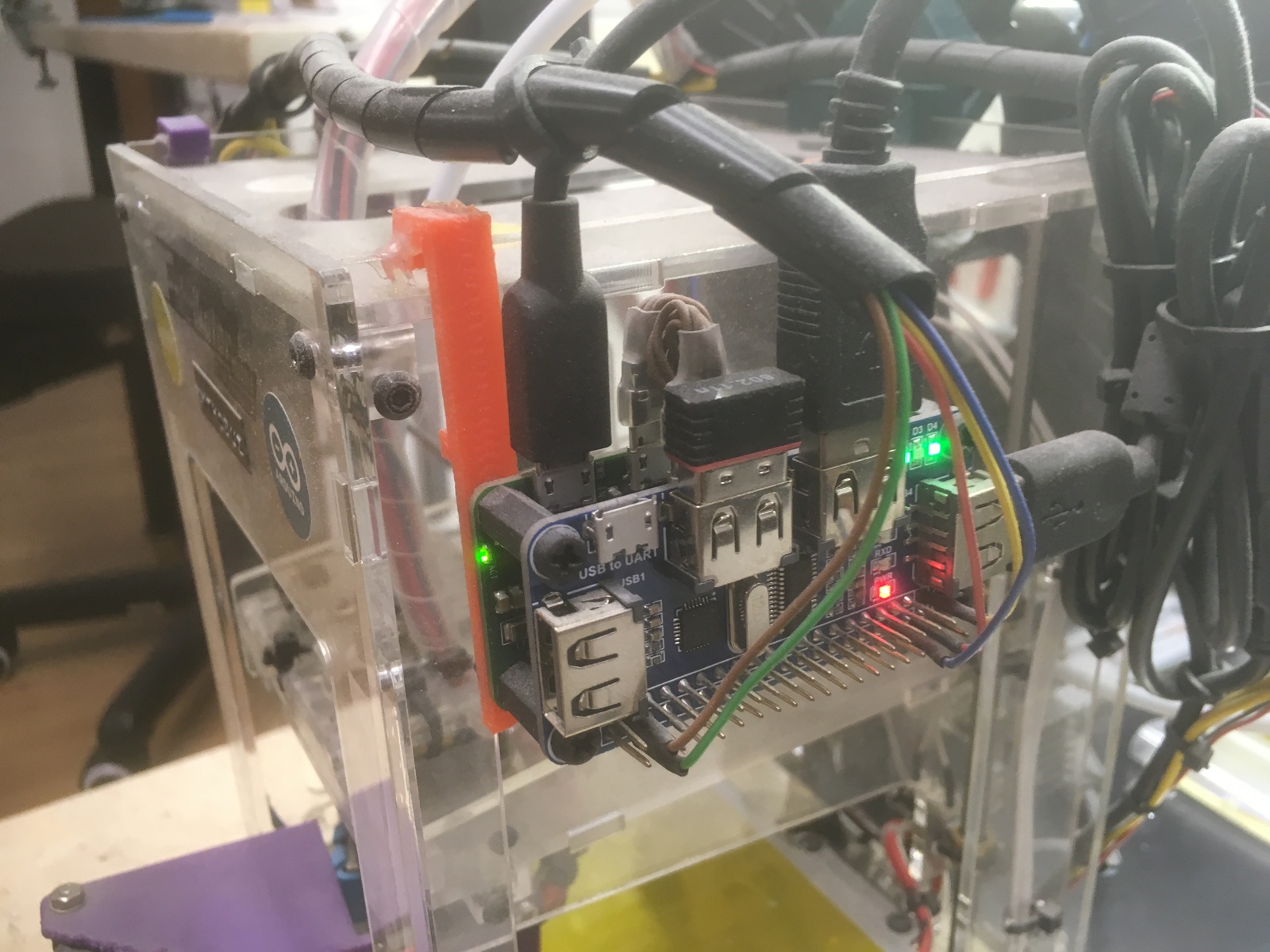
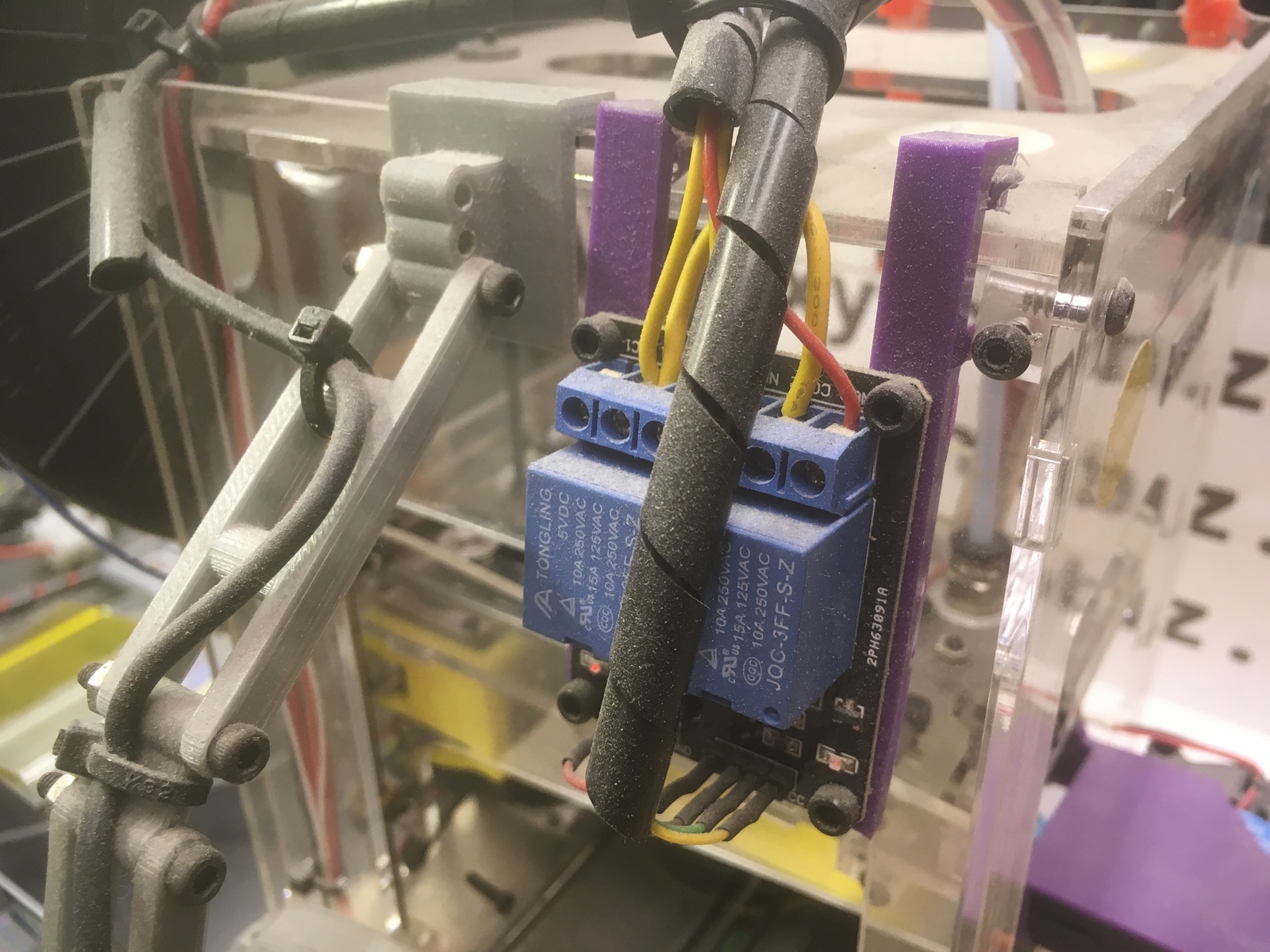
Relay Board
To fully utilize OctoPrint, it also needs a way to control the power supply to the printer. One popular method to achieve this is an ATX computer power supply. As I already had my power supply, and because the current of the small Fabrikator Mini is not that huge (and it's not switched under full load), I decided to use a simple two-channel relay board connected to the Pi.
Some more about controlling power supplies from OctoPrint can be found on this page about my OctoPrint setups.
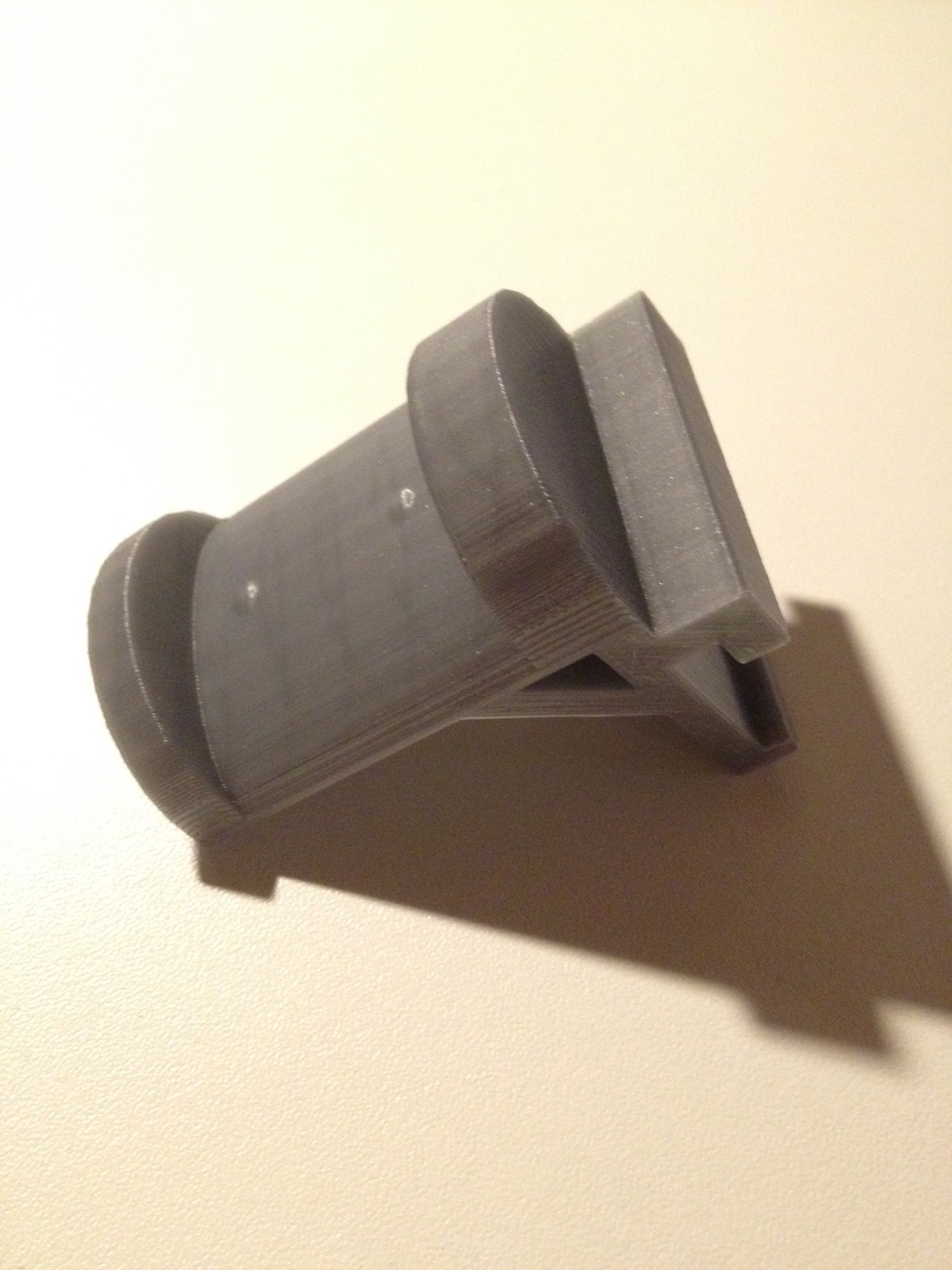
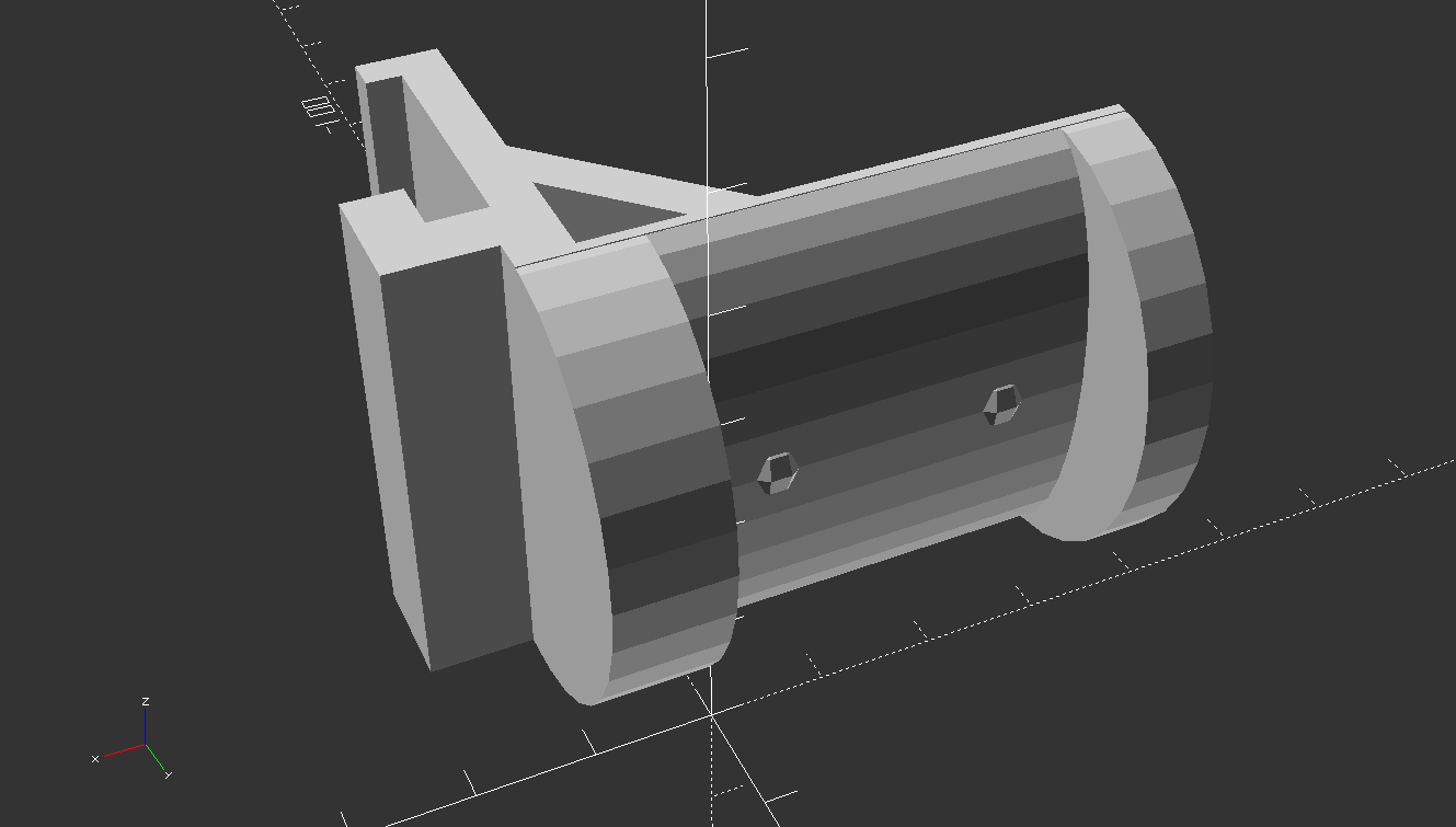
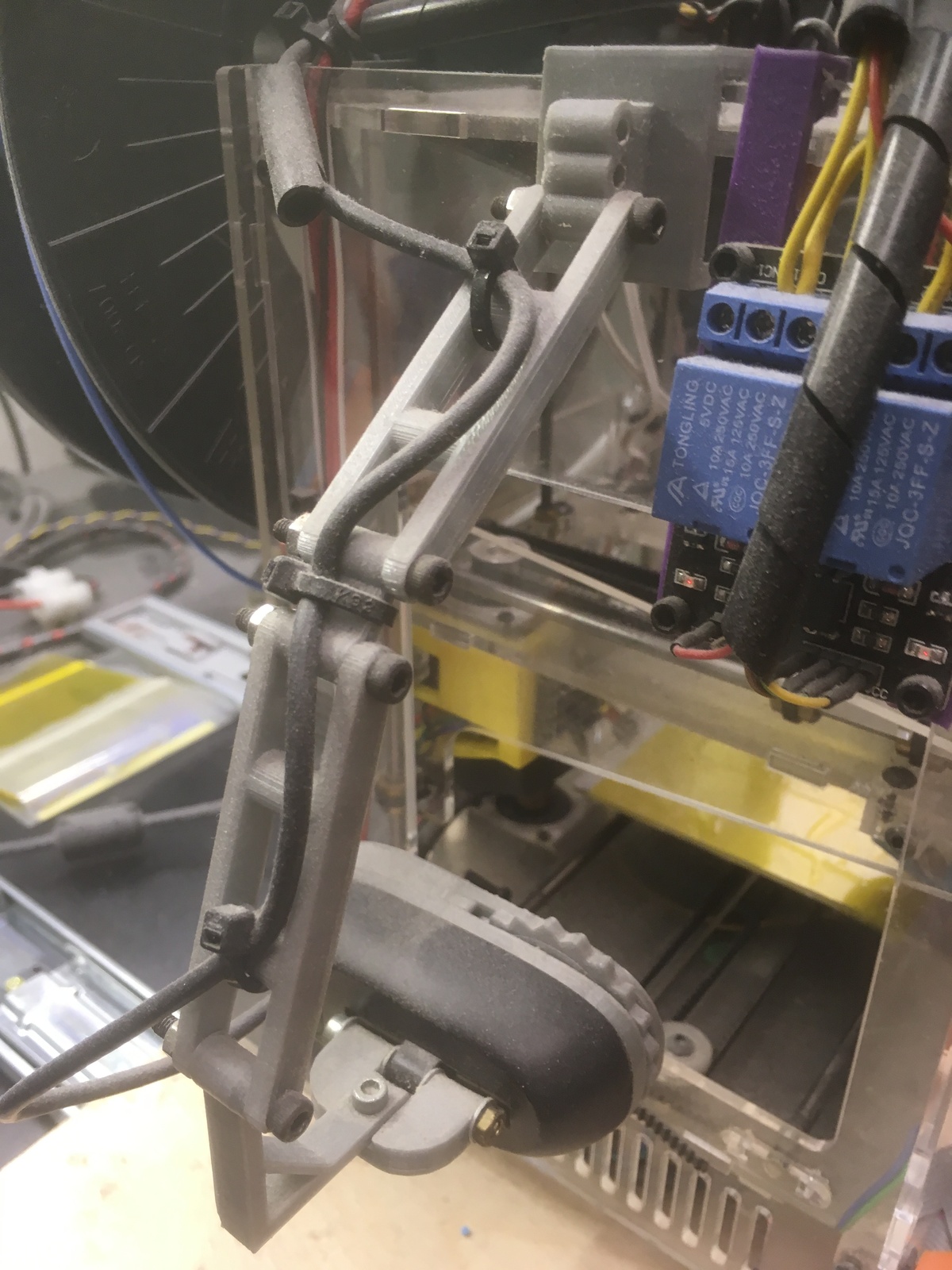
Webcam
No OctoPrint experience is complete without having a webcam connected to the Raspberry Pi. So I bought the, in my view, standard model for 3D printing needs: the Logitech C270. It is cheaply available on Amazon and can record with 720p. Even better, the front-plate can be removed and replaced by some 3D printed parts that allow the focus to be adjusted. Then I still had the problem of mounting the camera to the printer. So one of my first self-made designs became the Webam Holder: an attachment piece for the printer acrylic plates, some connecting bars and adaptor pieces, and the connector to the webcam.
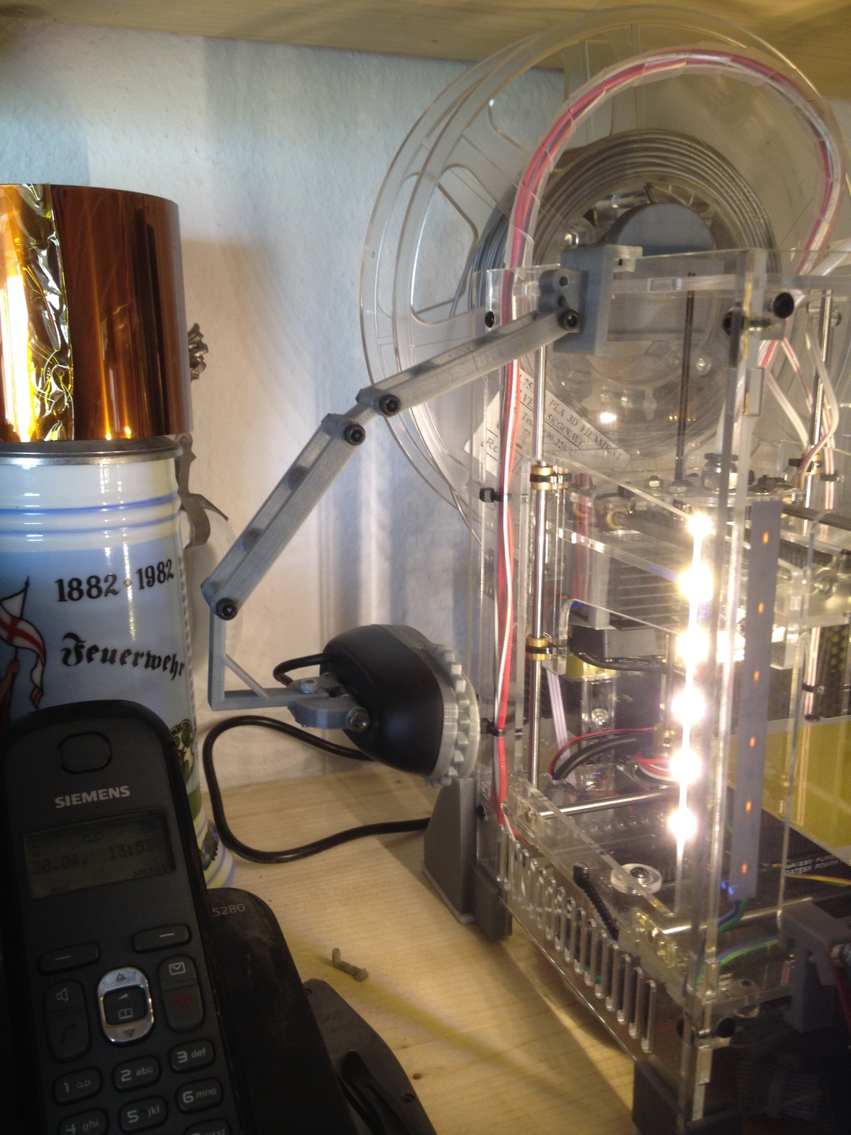
LED-Strip
Depending on where the printer is located, it can be very hard to see any details of the printing process. That's why one of the first modifications I did, long before using OctoPrint, consisted of sticking two pieces of white 12V LED-Strips inside to the backside of the front acrylic plate. Initially, I wired it to the main 12V connection to the printer, so the light was always turned on whenever the printer was powered. Nowadays I'm using the second relay connected to the Raspberry Pi Zero to switch the light on and off independently from the printer itself. This is very convenient to turn the lights off when printing overnight.

