CTC i3 Pro B
Experiences with and modifications to my chinese Prusa i3 clone
Project published on November 01, 2017.Last updated on January 27, 2022.
...back to 3D Printing overview
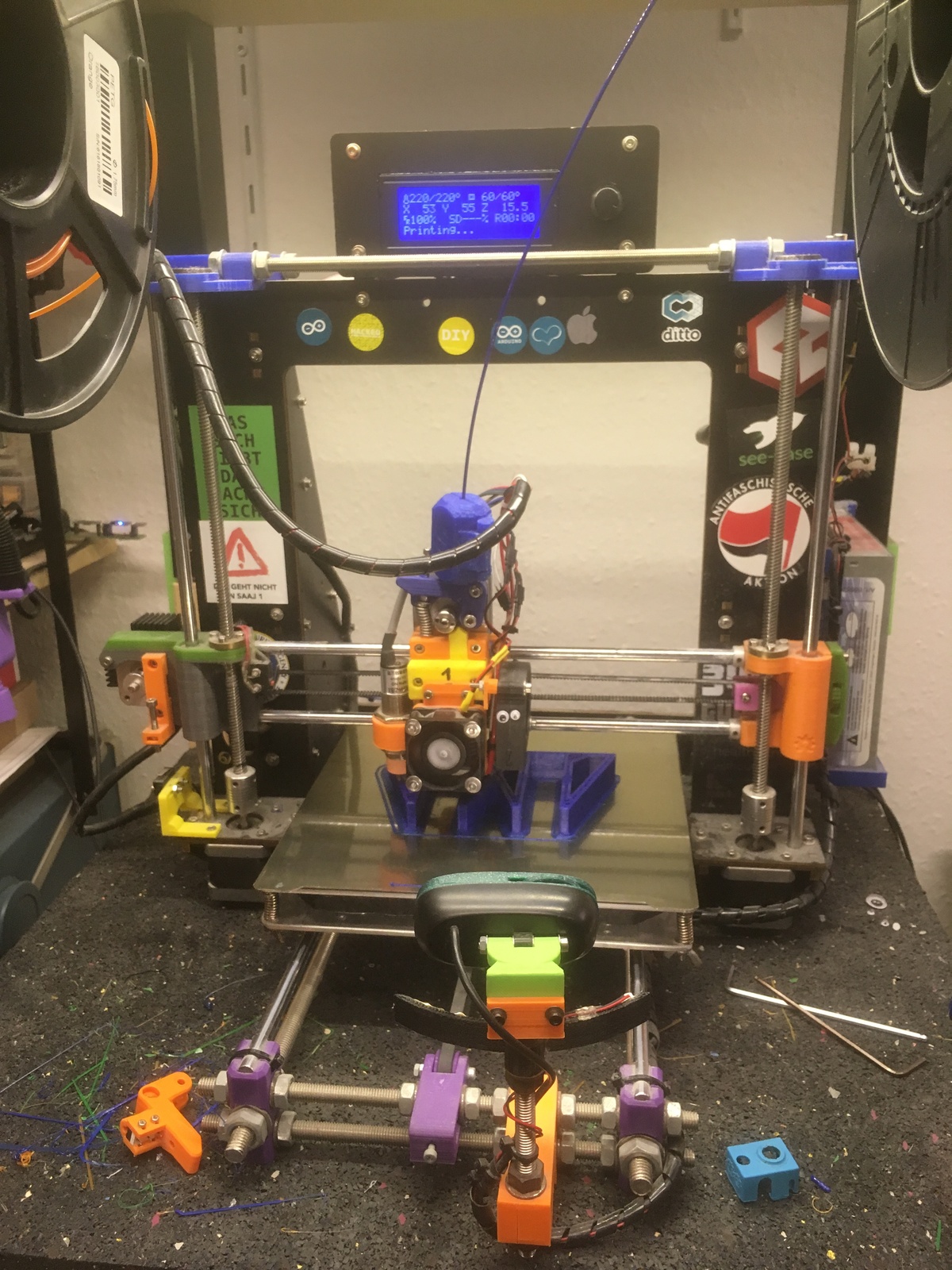
The CTC i3 Pro B is a very cheap chinese Prusa i3 clone. I bought it in November of 2017 for the surprisingly cheap price of 110€. The frame and motor mountings are made out of pieces of laser cut wood. Because of this, the frame flexes a lot, which is the main reason I would not recommend this machine today. Nonetheless, this is my main printer. I have used it a lot over the years and also modified many things on it.
The Y Axis mainly consists of M8 threaded rods and smooth rods, driven by a belt. The Z Axis also is made with smooth rods and driven by M8 threaded rods. The X Axis only has smooth rods and is also driven by a belt.
As a first step, I replaced the M8 rods of the Z-Axis with proper ACME thread T8 lead screws. Of course, to use these, I had to also get T8 nuts and print different Z-Carriages.
I also replaced all the ball bearings with IGUS RJ4JP-01-08 polymer bushings, replaced the fans and added silent TMC2100 stepper motor drivers to reduce noise.
In 2022, I replaced the wooden frame with aluminium extrusions in the style of the Anet AM8 mod. You can read about this on my i3 AM8 page.
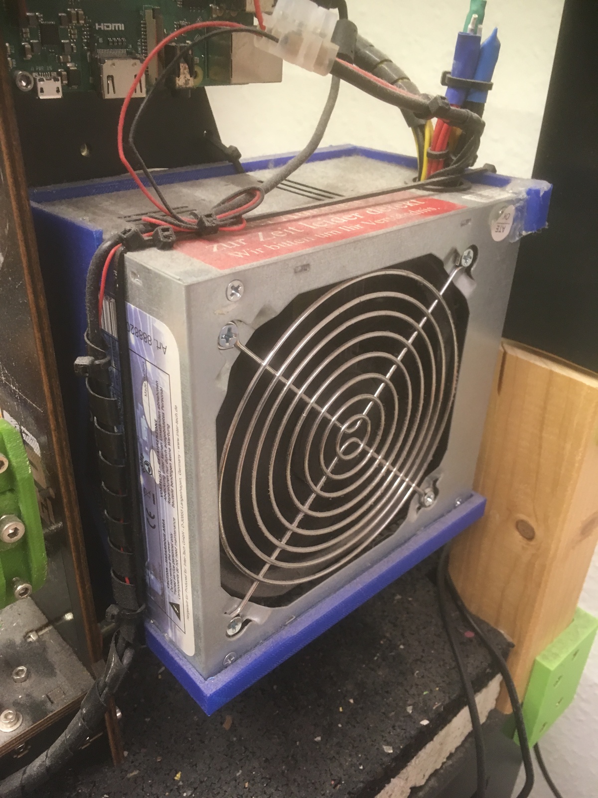
Power Supply Replacement
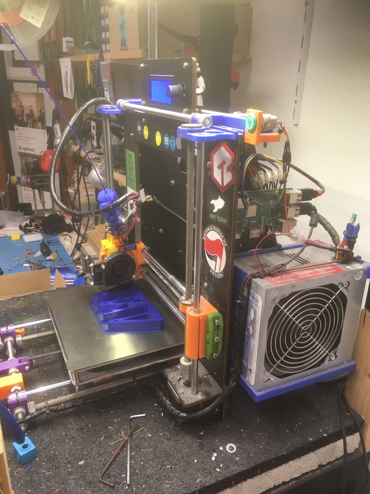
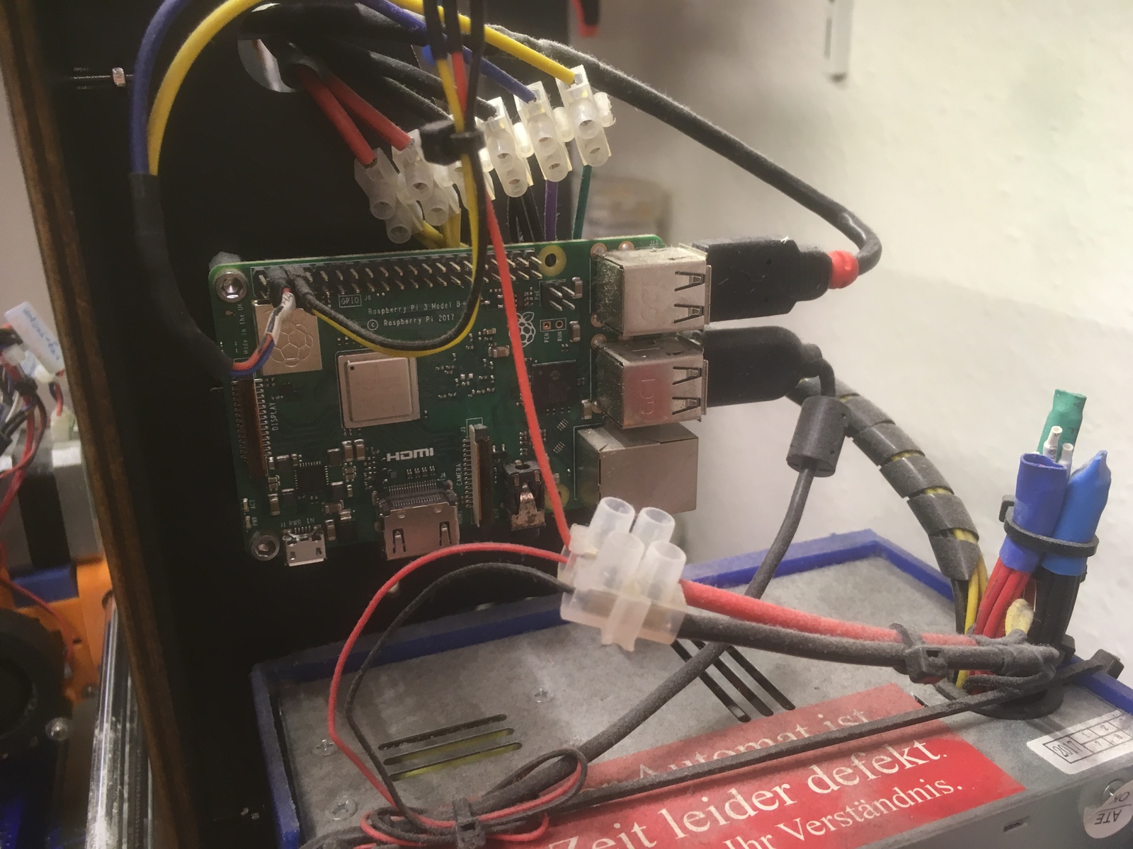
One of the first things I did was replacing the power supply with an ATX PC PSU. To mount it to the printer frame, I used "Anet A8 ATX mount" by corsara. This not only provides +12V to the printer itself, but can also power a Raspberry Pi with the +5V Standby power that is always available. That way, the Pi can use a GPIO to turn on/off the printer power using the green "Power On" signal of the ATX standard power supply connector. The standby power cable is purple. See Wikipedia for details.
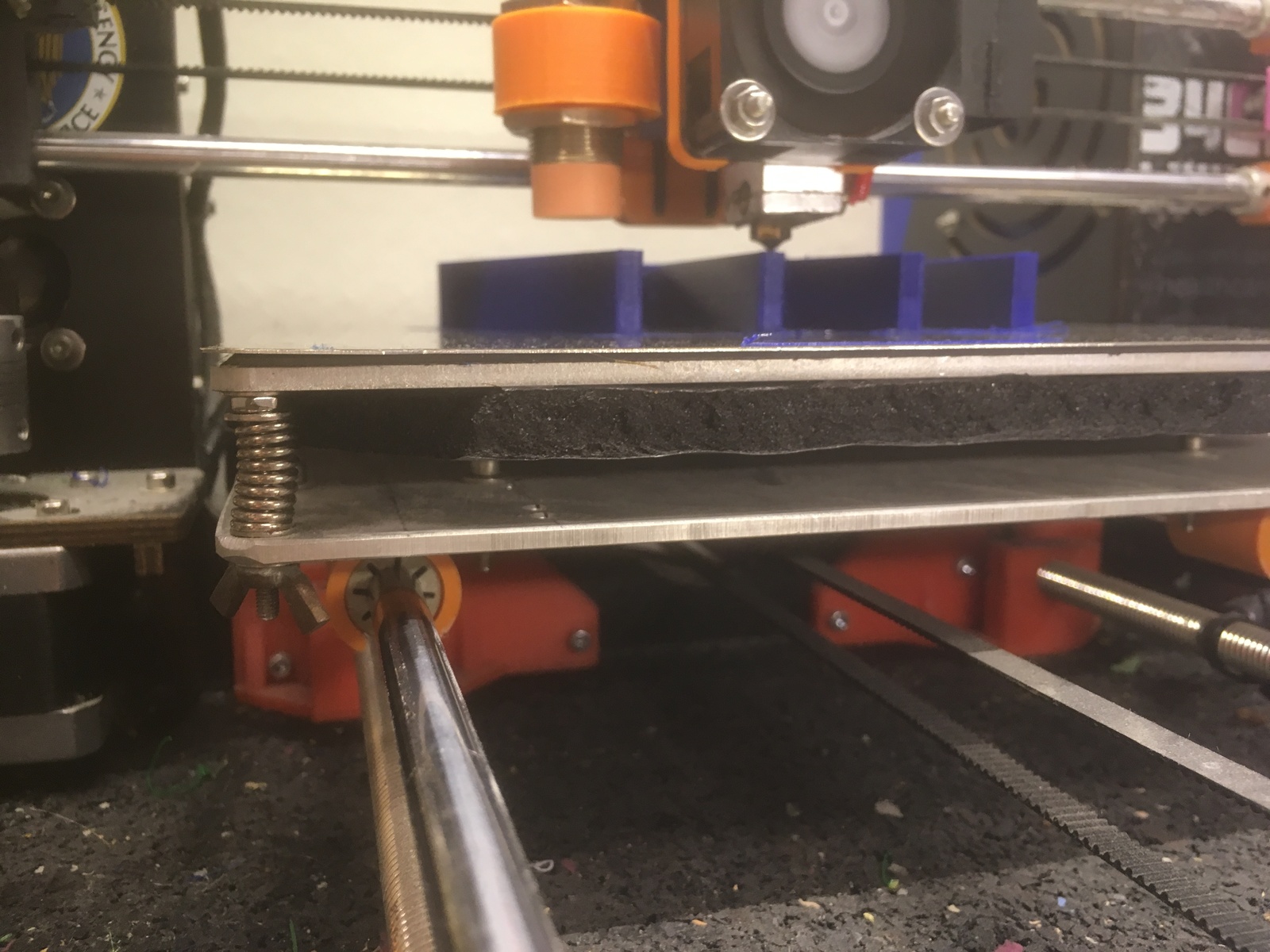
Heatbed Replacement
The original FR-4 heatbed is very flimsy and bends easily. For this reason, I replaced it immediately with a very commonly available replacement heatbed made out of 3mm aluminium, with 214mm x 214mm. Below it I mounted some self-adhesive foam insulation.
Print Surface
For the printing surface, I have tried many different options over the years. My first printer originally came with blue painters tape, which did not survive for long. My first replacement there was Kapton tape, which I am still using on the Fabrikator Mini.
For the CTC i3, my first attempt was using a plate of borosilicate glass, which I kept for a couple of years. Even though it has its problems with getting the first layer to stick and also needs clamps that reduce the available space, I was able to use it pretty successfully with PLA and TPE, as long as the first layer area was large enough or i was using a brim. But with PETG, I had serious problems getting the first layer to stick.
Next, I tried this UEETEK BuildTak clone. It works very well, the first layer sticks unbelievably strong to the rough surface. It even works too well. It is often difficult to get the print removed. I found myself orienting prints so the first layer area is as small as possible, so I could get it removed more easily. Even though that worked pretty well, and eliminated all first layer issues, I now had the issue of getting prints off without destroying them or the build surface.
Because of that, I next got the ERYONE magnetic build surface. The magnetic mounting works very well and the steel sheet sticks to the magnetic plate strongly. The surface has a sheet of maybe-fake-or-not PEI on top. This works relatively well for now, I would compare it to the Kapton sheet or the glass plate, prints don't stick too well, but with a large surface or brim it seems to work.
But it is still not perfect. As a next step, I plan to combine the magnetic plate with the fake BuildTak. I hope this may combine the positive aspects, having a first layer that sticks well, but still can be removed. But I have not tried that yet.
TODO photos
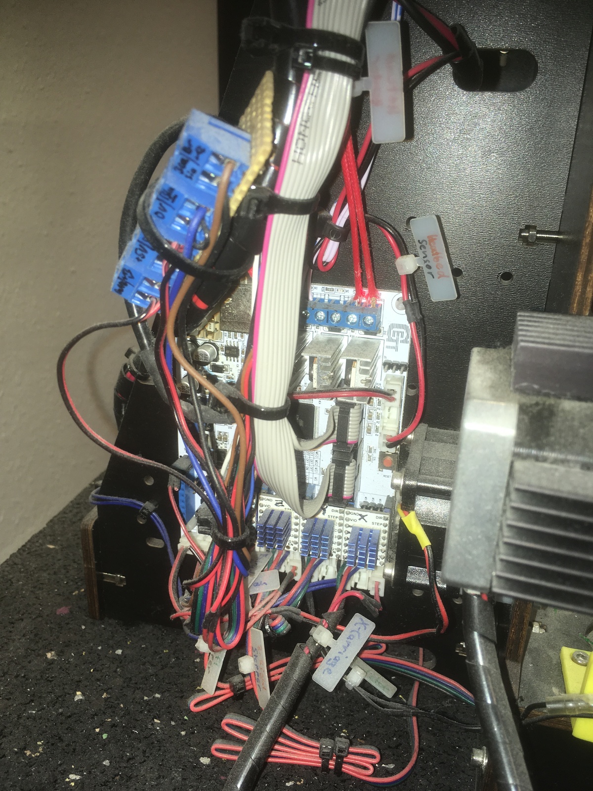
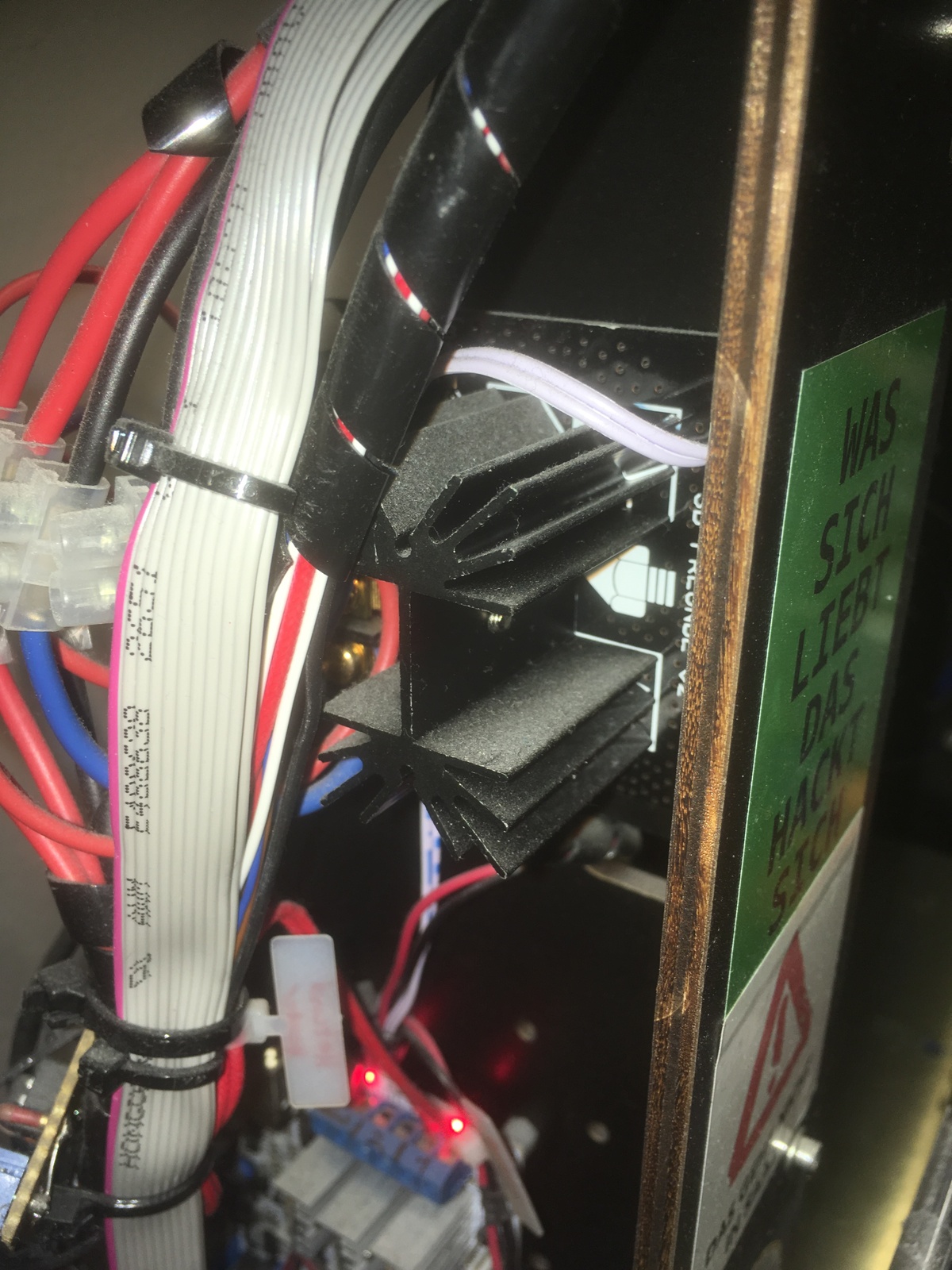
MOSFET for Heatbed
It is common knowledge that the heatbed MOSFETS on Anet A8 printers are not sufficient and present a fire hazard. Because my CTC-i3 has a different mainboard, I didn't think this problem applied to me. But sure enough, after a year or so of regular usage, the heatbed MOSFET, as well as some parts of the PCB of my mainboard stopped working and were visibly burnt. Because of this, I added the widely used beefy external MOSFET to power the heatbed.
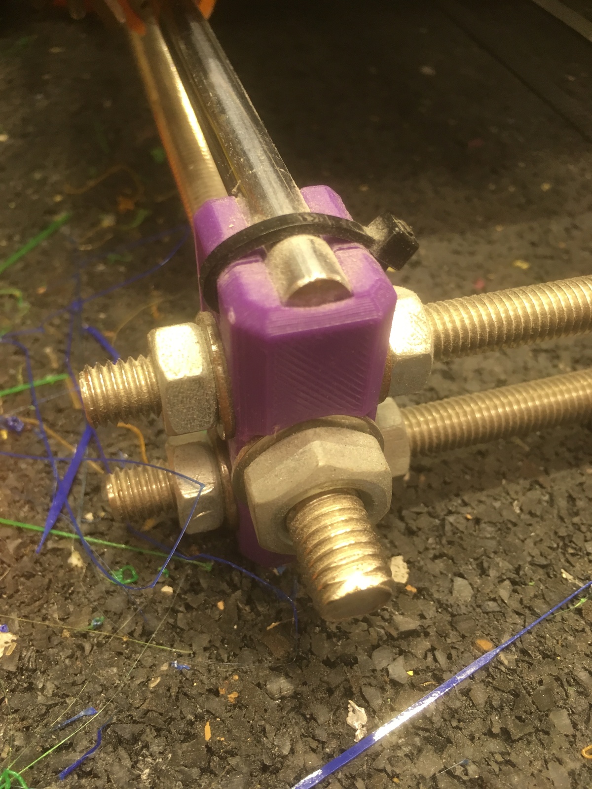
Y-Axis Replacement
To upgrade the Y-Axis and get rid of the wood pieces keeping the X distance, I printed the Y-axis files from the original Prusa i3 design. They can be found in the master branch of the GitHub repo, as in "y-corners.scad", "y-motor.scad" and so on. I got this idea from a YouTube video that I can no longer find unfortunately.
With these parts, the Y-axis distance are kept simply by two more M8 threaded rods. Putting it all together so the smooth rods are exactly parallel and the bed travels smoothly is a bit tricky, but can be done with some playing around.

Y-Carriage Replacement
Originally the Y-Carriage, which carries the heatbed, was also made out of thin wood, flexing a lot. When trying to achieve a print bed that is as level as possible, this is not good. So I simply got a properly sized piece of aluminium from ebay, drilled the holes for some small printed bearing holders and mounted the heatbed to it. This was easy and has worked very well as a replacement.
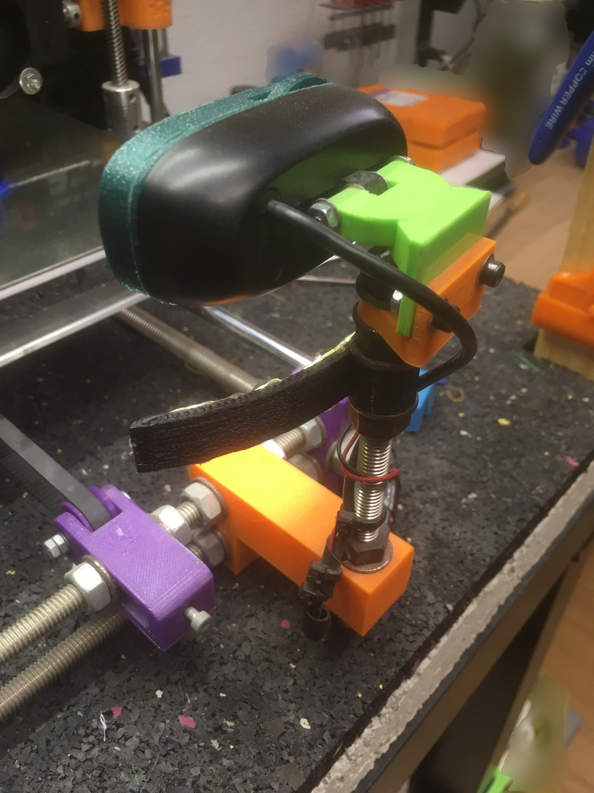
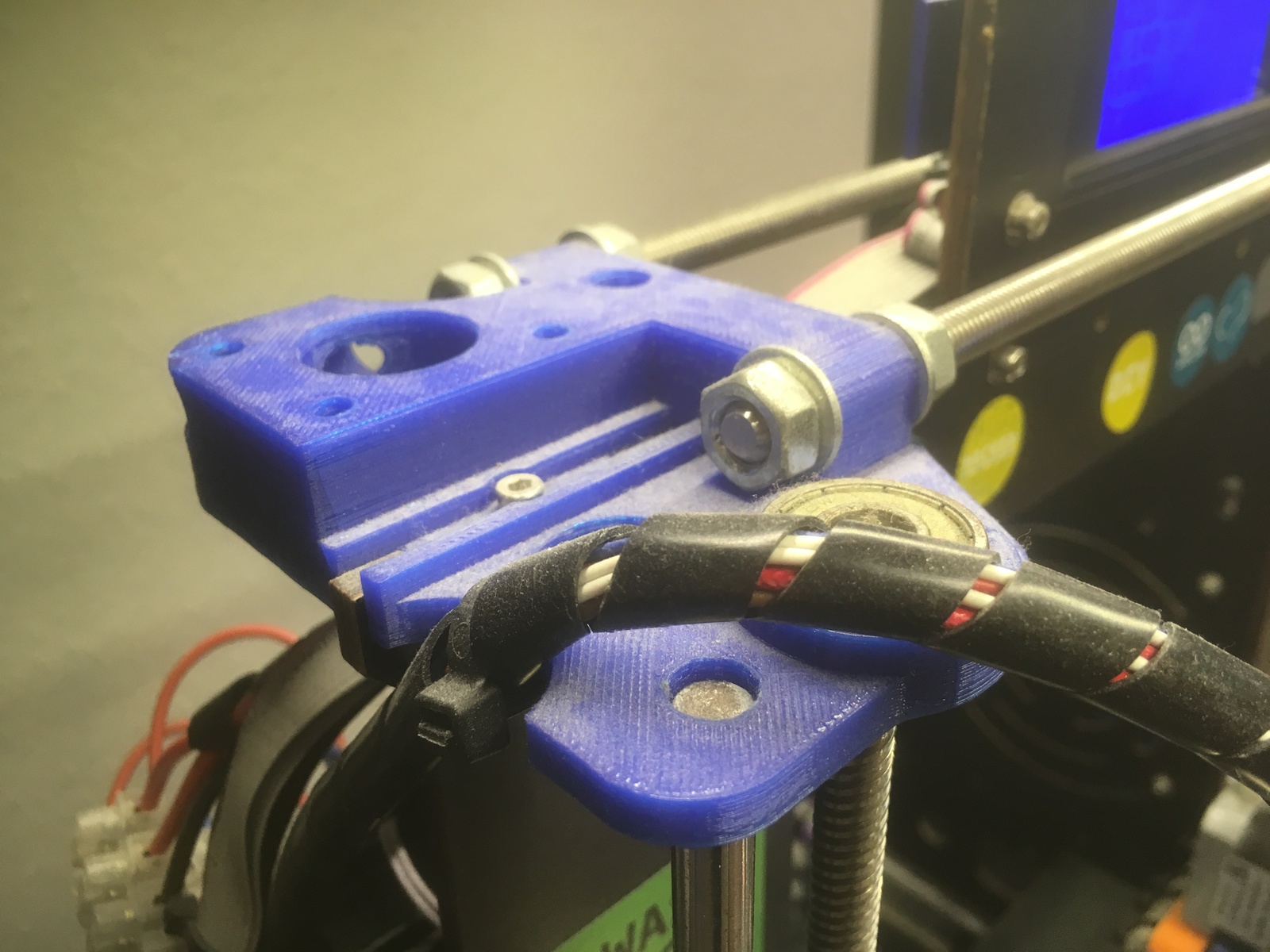
Y-Axis Webcam Mount
With the replaced Y-axis, it was easy to design a simple bracket that screws onto the front M8 rods. With another piece of M8 rod, I mounted a webcam. First, while I was still using an Orange Pi instead of a Raspberry Pi, I mounted the Orange Pi camera there. Later, after the switch to the Raspi, I also switched the camera to a Logitech C270. I also added another print that can hold a piece of LED strip under the camera, so you have more light for the picture.
The design files can be found in my Git repo.
Z-Carriages / X-Axis Replacement
Relatively early after getting my printer I replaced the Z-Carriages and the X-Axis. For this, I used "Smooth X-axis for Prusa i3 with Leadscrews" by MazaaFIN. However, I only printed the right Z-Carriage. For the left one, I used "X Axis motor mount for Anet A8 or Prusa i3" by Randino, because the X endstop switch mount better fit my next replacement. For the Z endstop, I have used "Prusa i3 ANET A8, Z Endstop Adjuster." by flyingferret which can be tuned finely and works great.
So my X-Axis is a bit of a mix-up, but it seems to work well and I have not had the need to replace anything else there since.
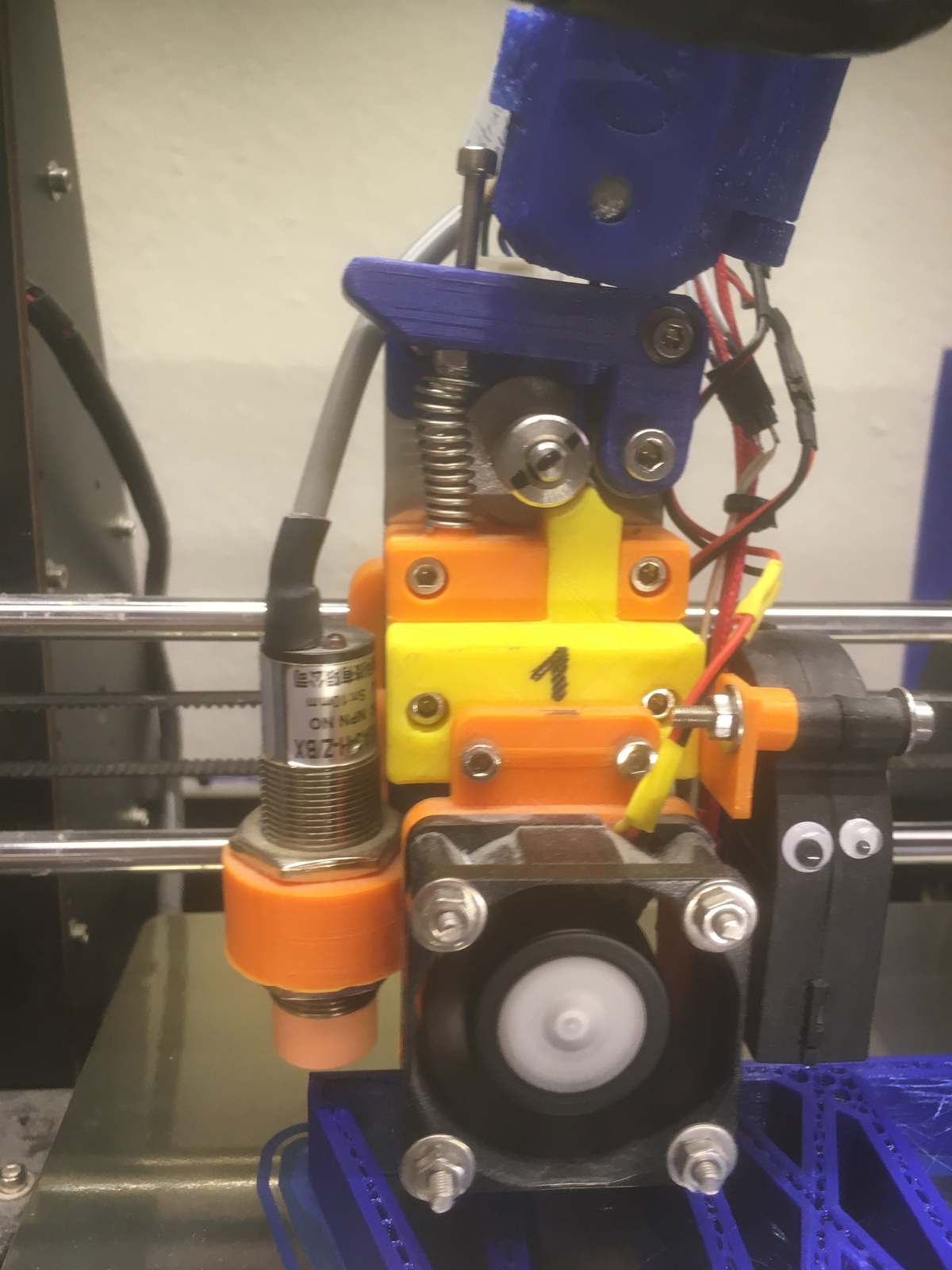
X-Carriage Replacement
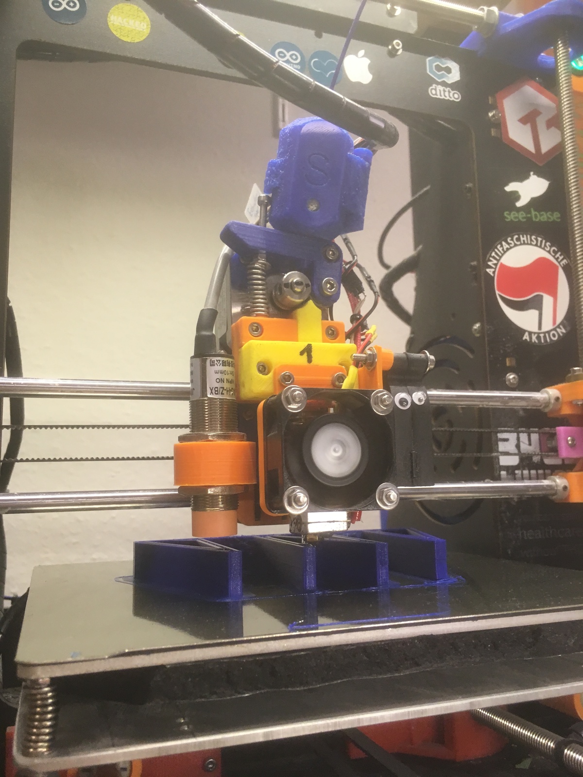
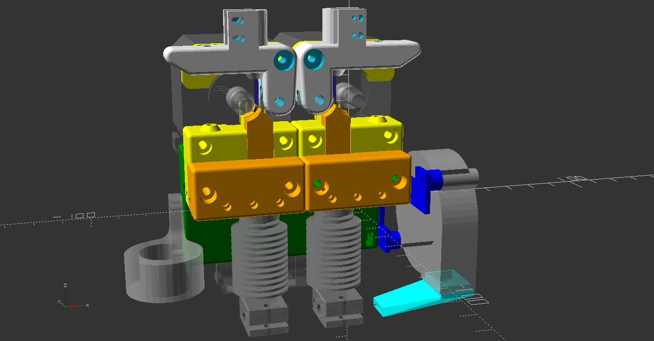
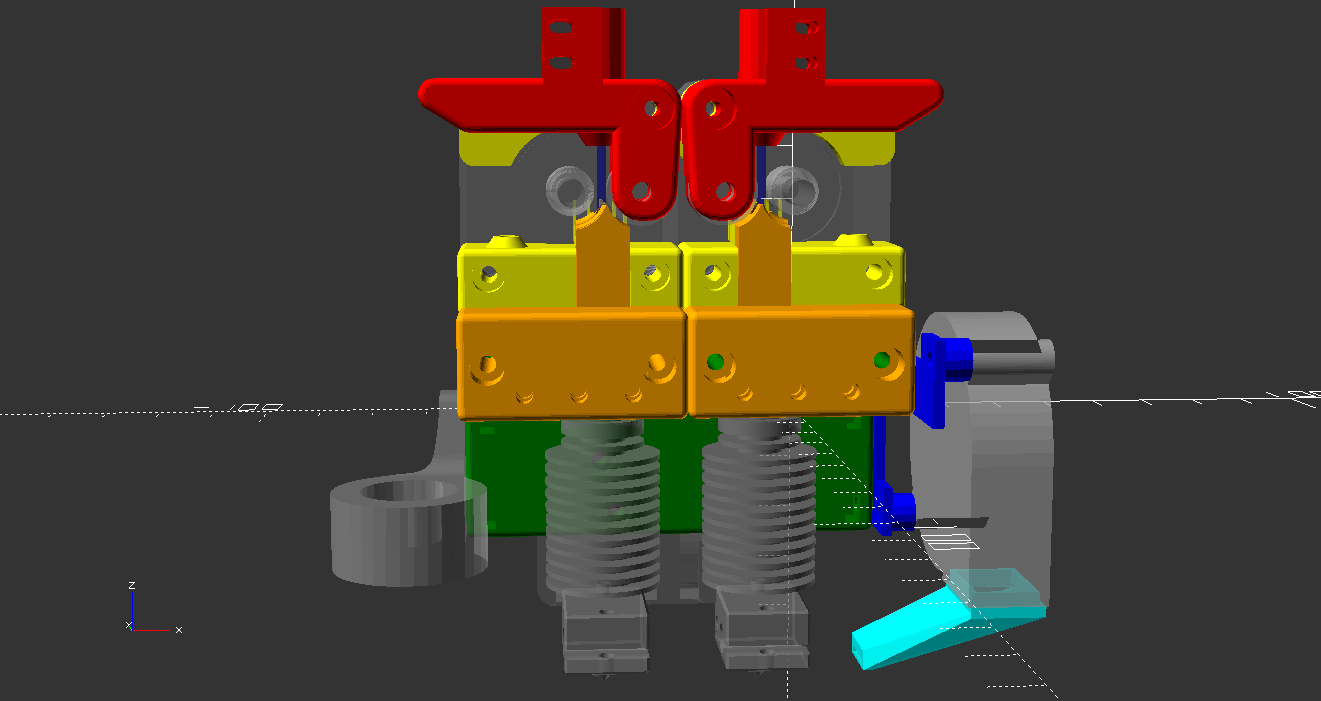
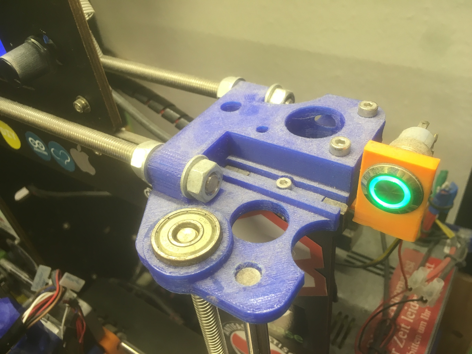
I replaced the X-Carriage with the great "Customizable direct drive extruder for E3D v6 hotend for Prusa i3 / Wilson / Geeetech" by gtcdma. It is a well-designed and sturdy hotend mount with a direct extruder. It is written in OpenSCAD, so I modified it a bit, making my own custom filament and hotend fan mounts. To mount a capacitive bed leveling sensor to it, I used "Mount for capacitieve sensor 19mm" by Slavulj.
The files can also produce a dual-extrusion design. I tried it as well and ran it for a while. But I have since reverted it to a single hotend. I was not really using the dual-color feature and it has the usual problems of two hotends mounted side-by-side on the same height. The second, unused, nozzle tends to collide with the print causing many different problems. But other than that and with some tuning it worked well and I was getting some good two-color prints.
If you use a strong spring for the extruder arm to get a high contact force without slip on the extruder, I suggest printing it with PETG at least, because the PLA I was using originally warped after a while, causing the filament to jump out of the extruder gear.
For the extruder motor, I used a NEMA17 with only half the usual height to increase clearance to the top frame brace, which is described below.
My modified design files can be found in my Git repo.
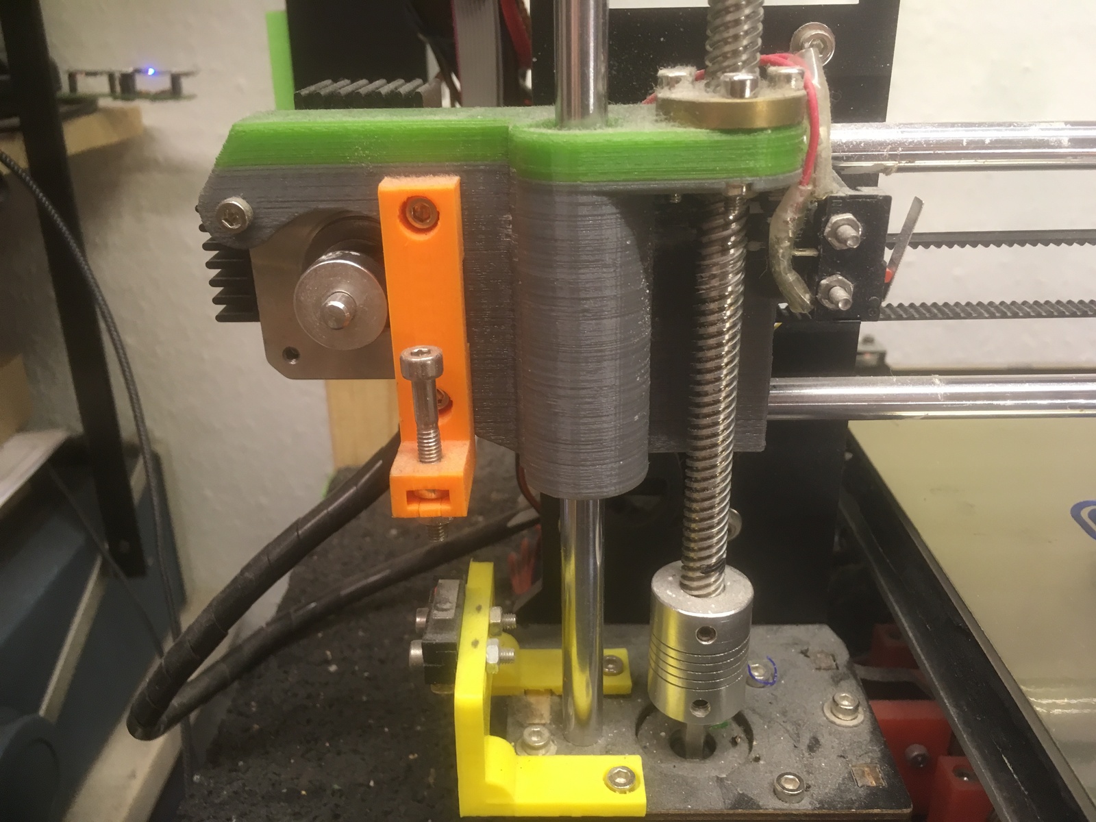
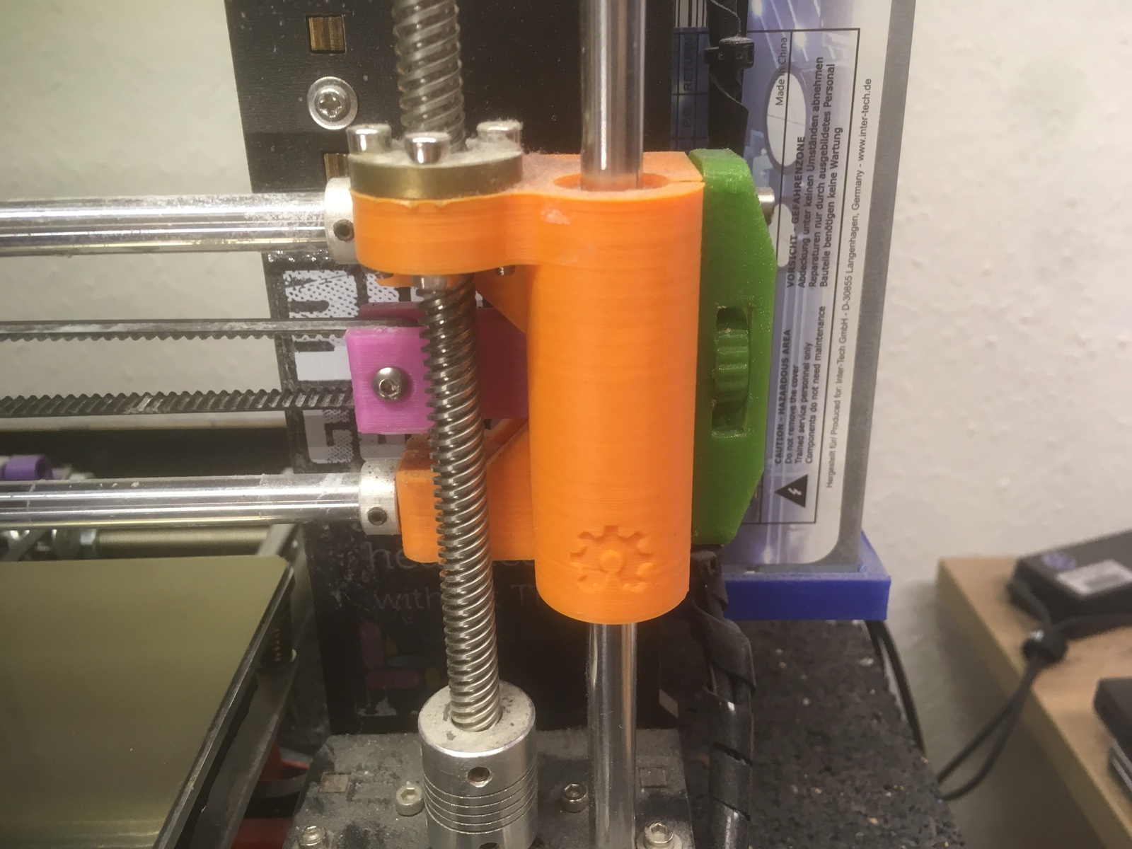
Z-Axis Top Fix
Frame Braces
Raspberry Pi Addon
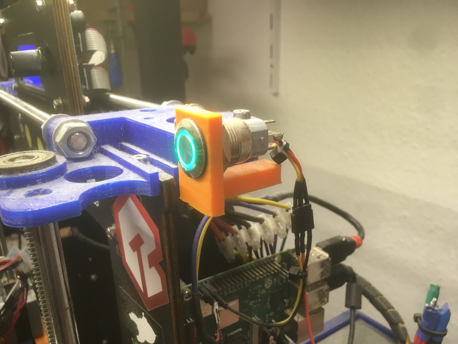
Power Button
To use the power button with the Pi, see my page about setting up OctoPrint.