Reviving a broken bench top power supply
Using a chinese RD DPH-5005 buck/boost module
Post published on June 25, 2021.About two years ago, in 2019, my Basetech BT-305 bench top power supply decided to give up. It no longer showed the correct voltage, only displaying zero, and the regulation did not seem to work anymore either. I noticed that when a battery I tried to charge started smoking... 😰
Because of all the hassle of moving, I moved it to the healing bench where it stayed for a while. Some months ago, I decided to do something about it, and went to the Conrad Support. I originally bought it there, and they still sell it today. They had me send it in, but then decided they couldn't do anything about it.
Some years earlier I saw a video on the EEVblog YouTube channel about RDTech power supply modules. So I decided to give them a go and ordered the DPH-5005 module.
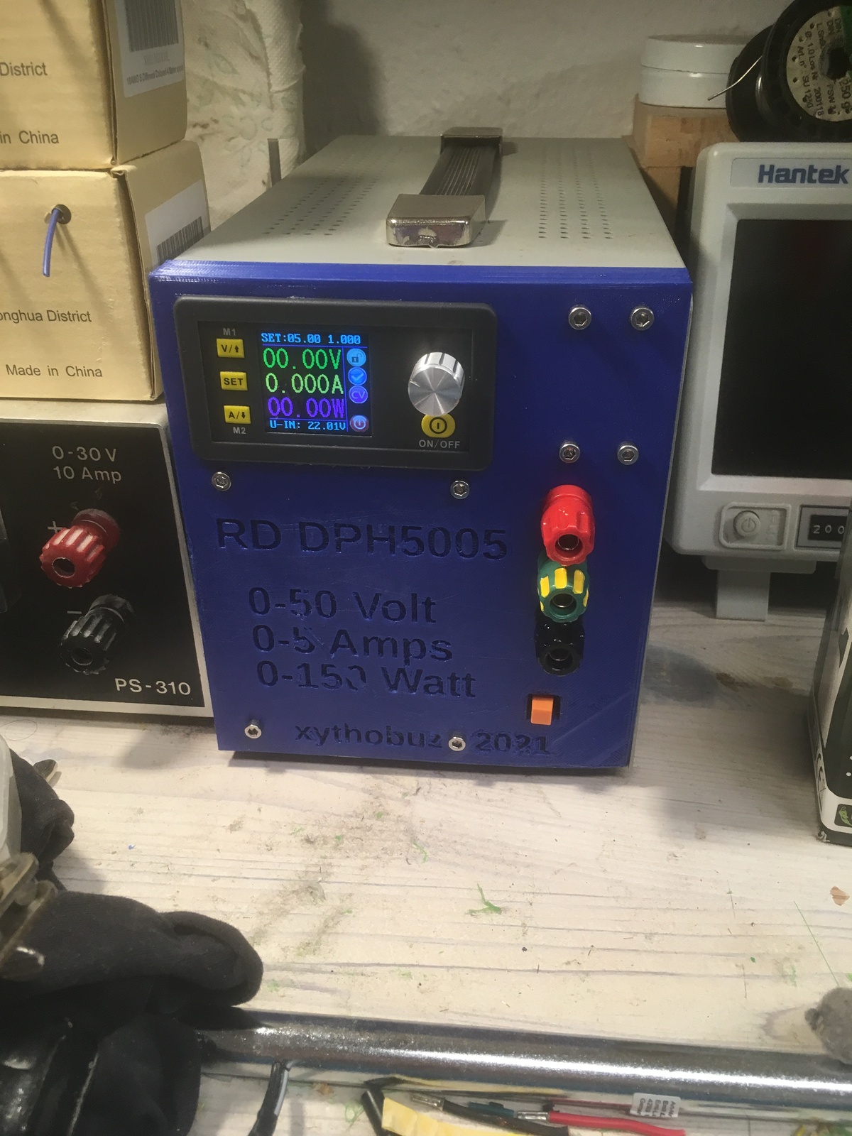
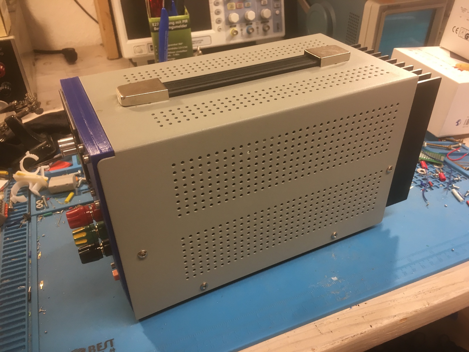
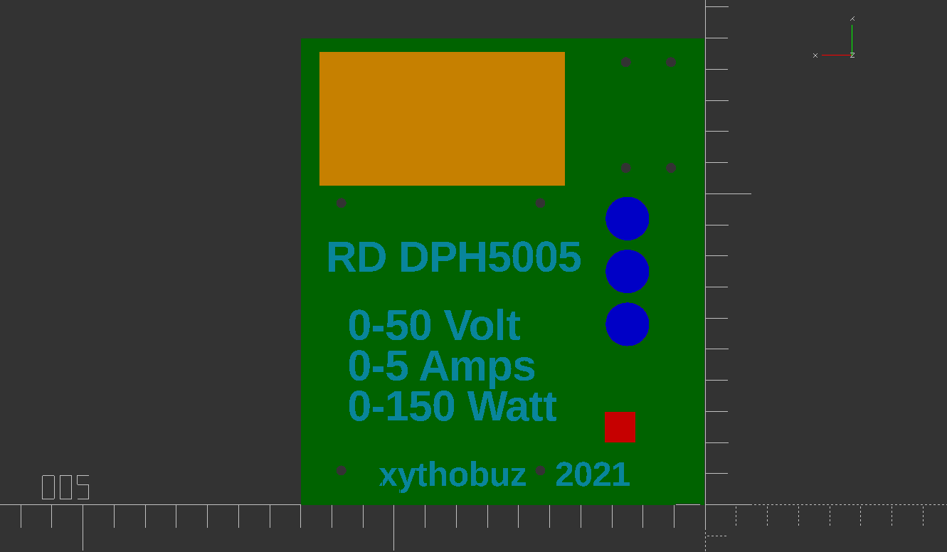
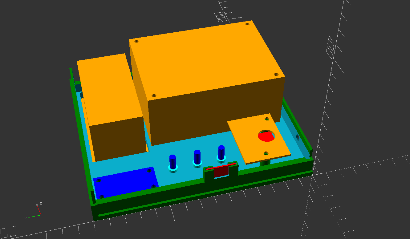
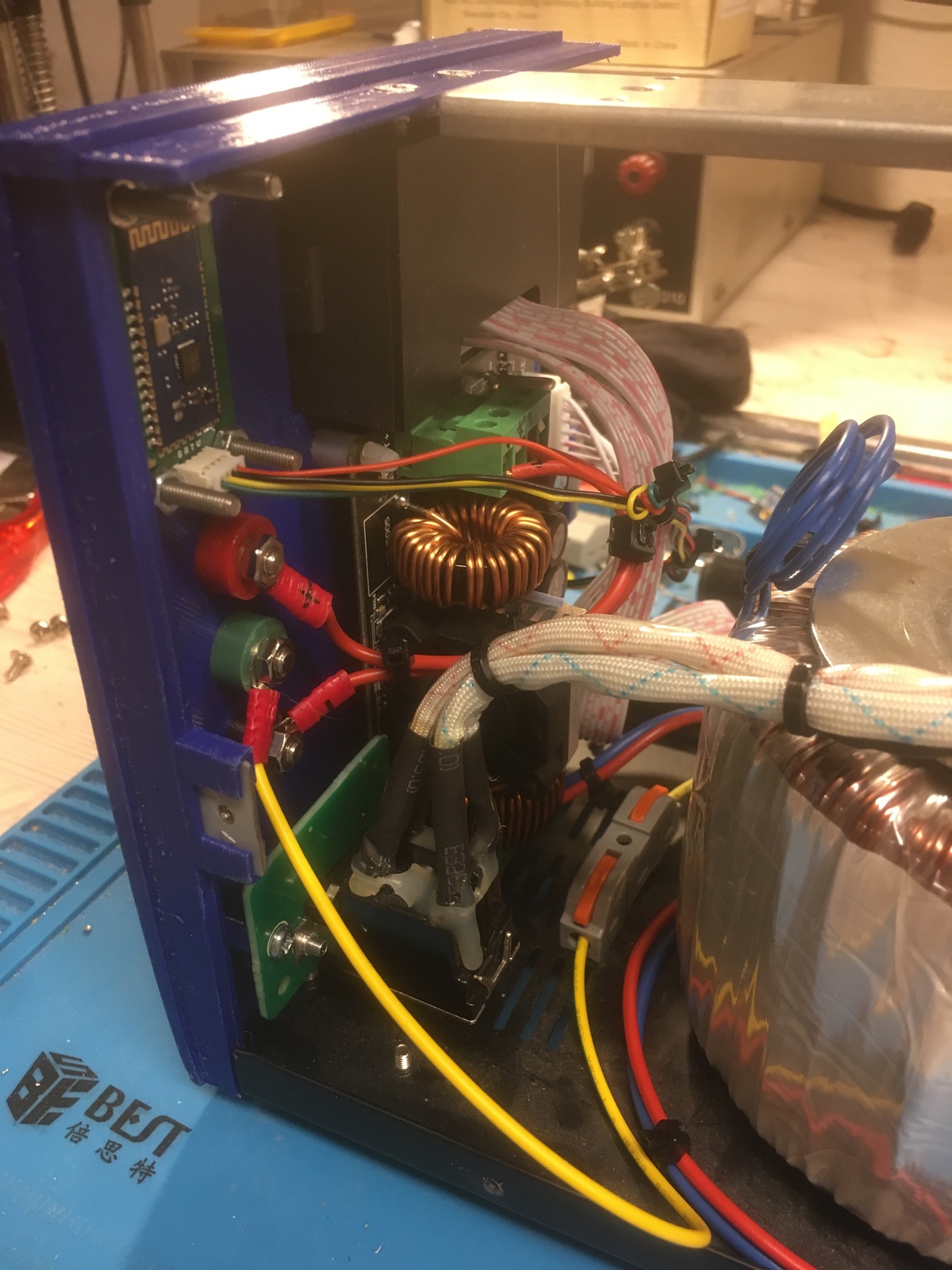
As you can see, I simply replaced the front panel of my existing power supply, re-using the transformer and parts for the rectifier. On the 3D printed replacement front, I mounted the display module as well as the buck/boost module itself. I also kept the original power switch, but added new output connectors.
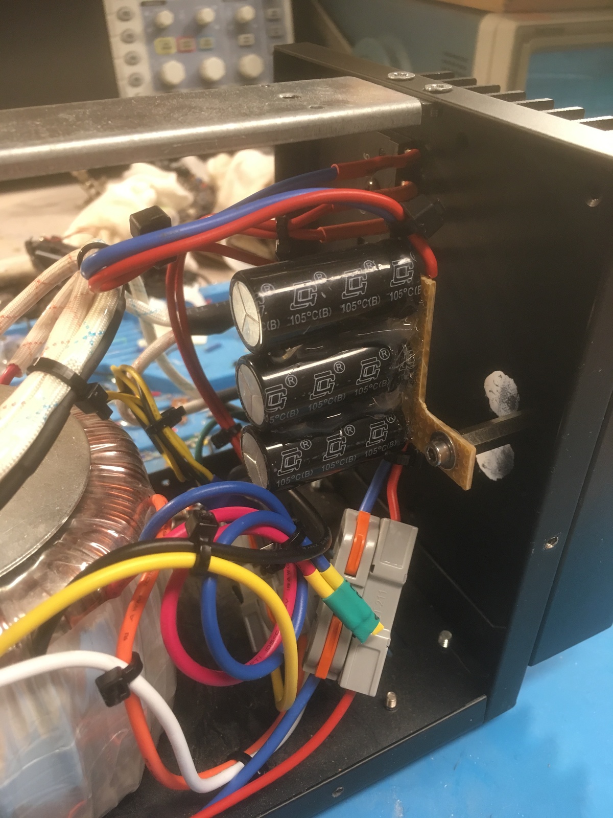
The rectifier of the original power supply consisted of a PCB mounted to a big heatsink in the back. It had some relais to switch between the different windings of the transformer, as well as the switching transistors and the rectifier. I desoldered the diode package and the capacitors. The diodes are still mounted to their original spot on the heatsink, with the leads simply soldered on. For the capacitors, I used a piece of strip-perf-board I had lying around, mounted with a spacer to one of the existing, now empty, holes of the heatsink. I used two strips of copper for each of the positive and negative poles, with a thick layer of solder on top so it can easily carry the current.
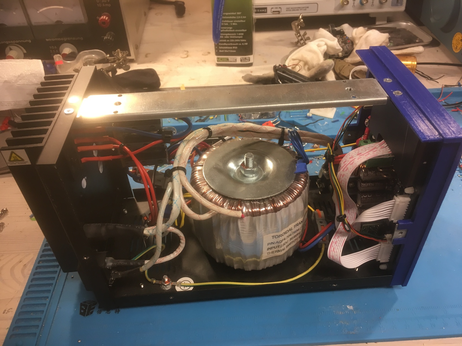
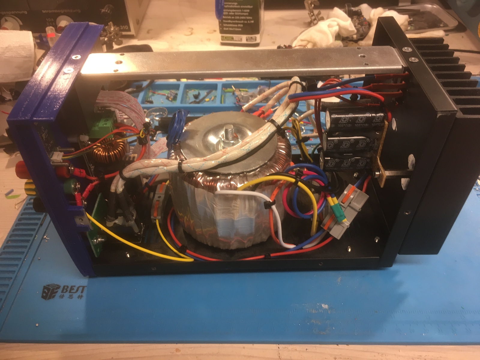
Figuring out the details of the transformer was a bit of an issue. It seems to be a specially made transformer, just for this power supply. Even though it has an identifying label, it contains no usable information, and the numbers on it lead nowhere on Google. So I first measured the resistance / continuity (while powered off and unplugged of course!) to determine which wires are part of one coil. Turns out, there are two main output windings, one with only the two outer connections, and one with a bunch of center taps. I connected two ends of the two windings, and used the outer-most connection points, to get the maximum voltage, which is a bit less than 40V AC, or 50V DC rectified.
This is also where I made an error in the selection of the DPH-5005 module. I specifically selected it because it can also boost the voltage up, instead of only stepping down. I did this because I wanted to get the full range of 50V, thinking I only had 40V input voltage. However, I forgot to consider that the rectified DC voltage is higher than the AC voltage. So I would not even need a boost module to reach the 50V output voltage. Of course, it still works fine that way.
For the output connectors, I ordered some proper Hirschmann PKI10 A Polklemmen. The original connectors used on the power supply are of the safety-4mm-banana-plug style. I don't even own a cable like that, but I sometimes need to connect a bare wire, so these fit my use case much better.
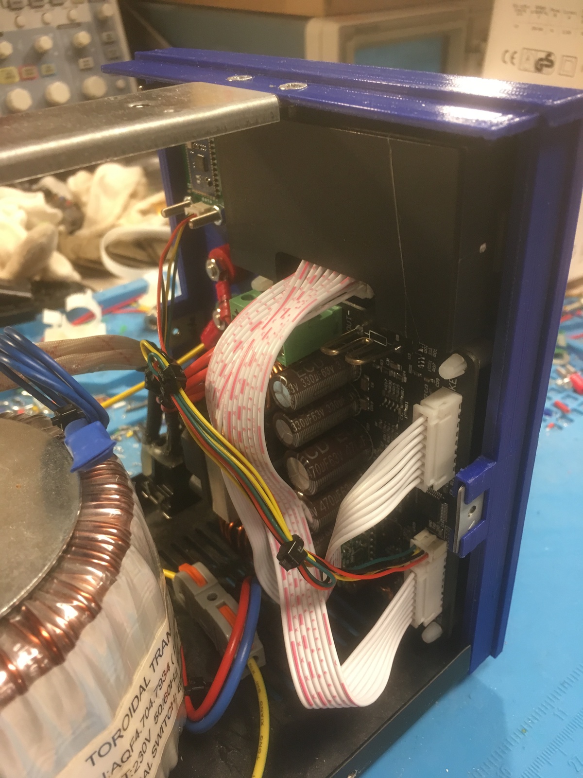
The DPH-5005 also has a Bluetooth or USB option. They both come in the form of a small extra PCB, with either a Bluetooth module or a USB-Serial chip. I added mounts for the Bluetooth module in my design.
The software 'rdserialtool' by rfinnie can be used to access the device via the serial port over USB or Bluetooth. I have tested this with the Bluetooth module and it seems to work as expected. Also see the sigrok wiki for some more about the protocol and available settings.
My 3D design for the replacement front is available in the Git repo.

