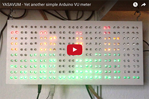
YASAVUM - Yet another simple Arduino VU meter
Simple MSGEQ7 stereo audio visualizer
Published on May 03, 2016.Recent activity on GitHub: 
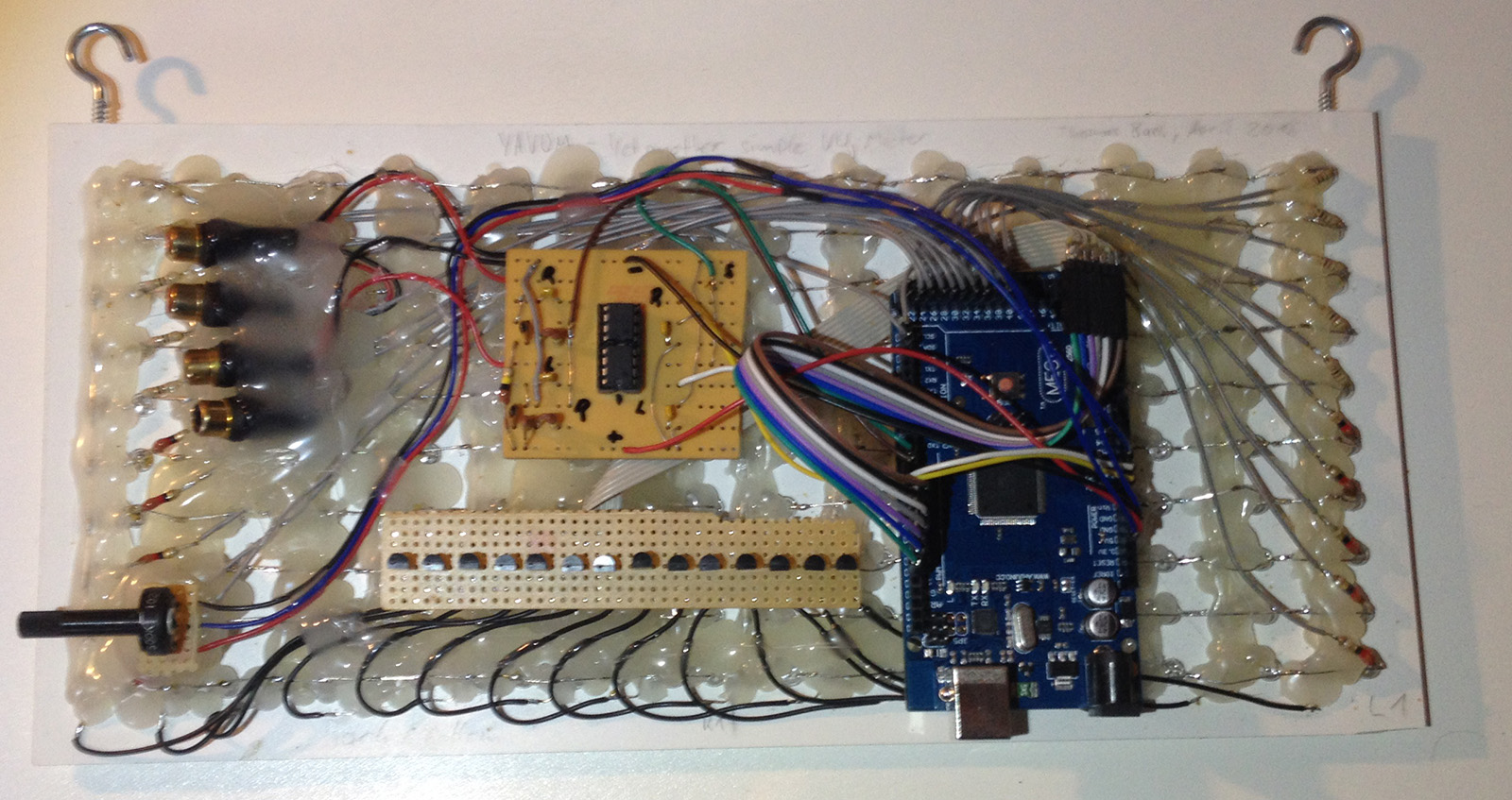
This is a simple VU meter using an Arduino Mega with two MSGEQ7 ICs and a multiplexed PWM controlled LED display with 14 by 10 "pixels", in my case made up of two LEDs each, with adds up to 280 LEDs.

Hardware
The Hardware, as well as the Software, basically consists of two parts: the MSGEQ7 stereo spectrum analyzer and the LED display.
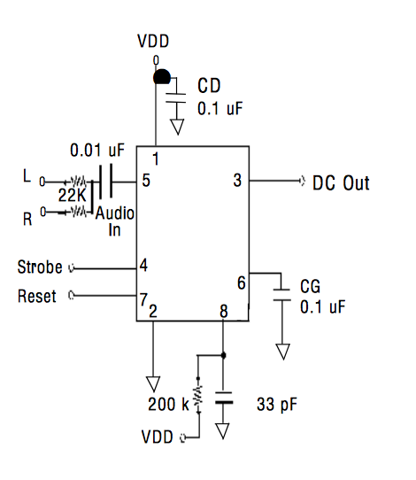
MSGEQ7
MSGEQ7 is a nifty little IC that can split an analog signal into different frequency bands. It will then put out the average amplitude for seven different bands in the audible range. The basic circuitry from the datasheet is more than enough. Simply build it up two times, connecting the Strobe and Reset lines of both ICs together, so you have two inputs (Strobe and Reset) and two outputs (Left and Right). You can connect any kind of line level audio connector, I've used cinch but you can also use 3.5mm headphone connectors.
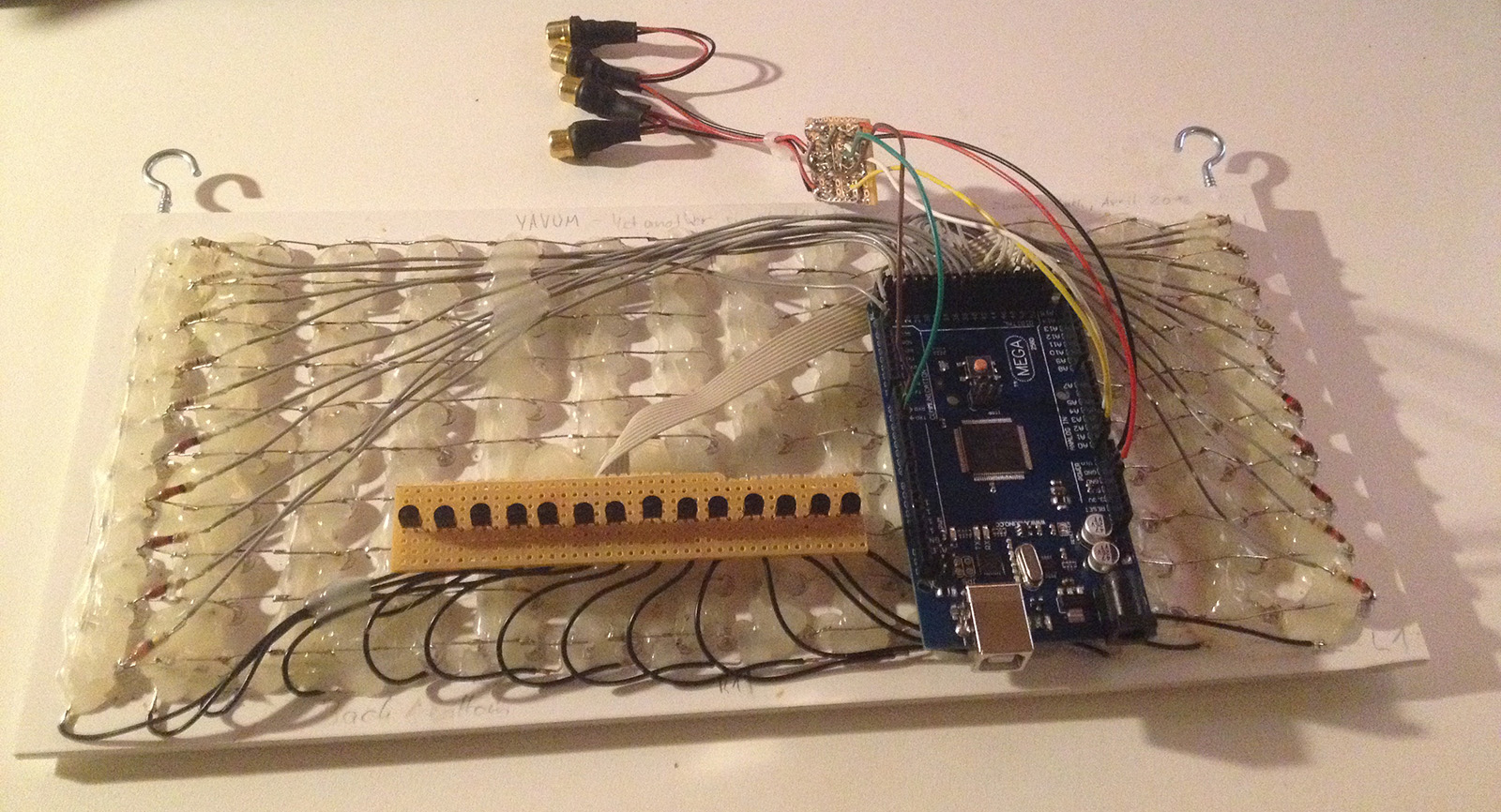
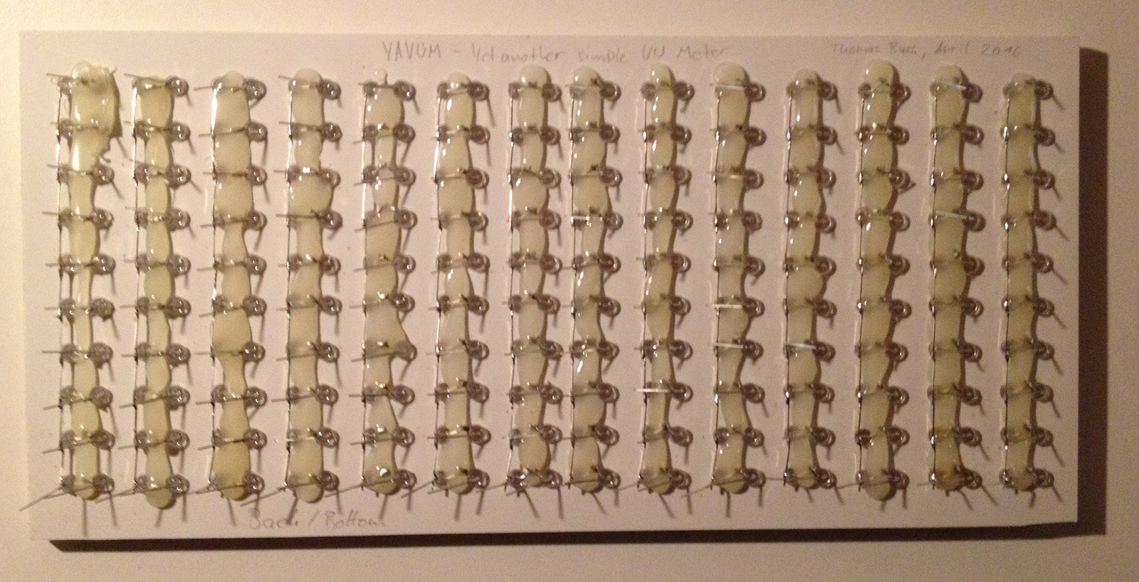
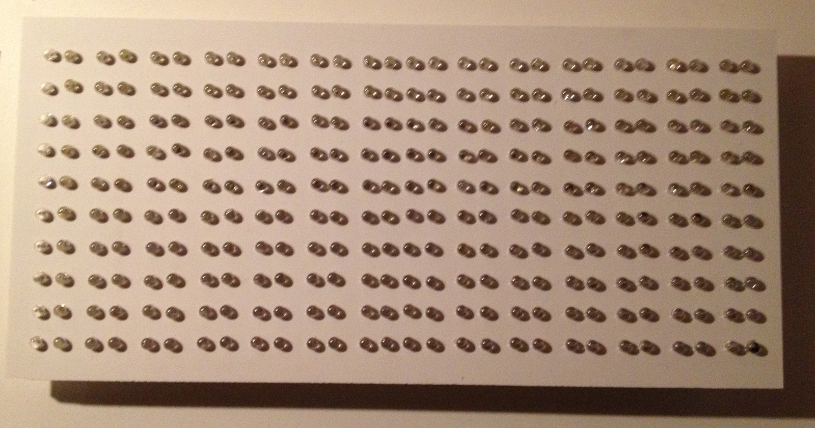
LED Display
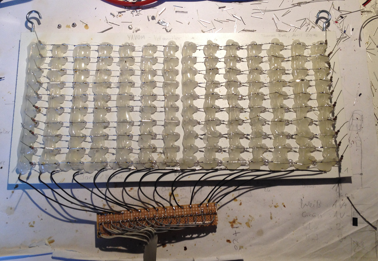
I'm using two LEDs per 'pixel' and trying to achieve maximum brightness, so I've decided to drive each pixel with 20mA, which is the maximum the Arduino Mega can provide on each of its pins. The anodes of all LEDs in a horizontal row are connected together and, over a single resistor, go directly to the Arduino. The display is split in the middle, so each half has 10 connections to the Arduino, resulting in 20 pins used for the rows alone. The resistor value depends on the amount and type of LEDs used. For my orange and red rows, I've used 50 Ohms and for the green rows I've used 10 Ohm.
The cathodes of each vertical column are connected together, and to ground over a N-Channel MOSFET. I've used the 2N7000, as it is able to be driven from the Arduino pins without any additional components. I'm using 14 of these, one for each frequency band on each channel, but one Arduino pin is connected to two MOSFETs at the same time, for each channel. This means there are 7 pins used on the Arduino for these.
Software
Get the current version of this Arduino Sketch from the YASAVUM GitHub Repository!
You should be able to read and understand this Sketch from top-to-bottom without much problems. It begins with the Configuration section. Here you can set the display refresh rate, timing parameters and enable or disable features like PWM control, the maximum bar and the noise filter.
You can add zero, one or two analog potis and assign them as brightness or gain control.
At first I simply controlled the MOSFETs using digital I/O. Later I've added PWM control to be able to set the brightness. This is using all available Timers in the Arduino Mega. They run at full speed, which seems to be plenty to provide full 8bit brightness control.
The code for reading the MSGEQ7s has been taken without much modifications from my LED-Cube project.
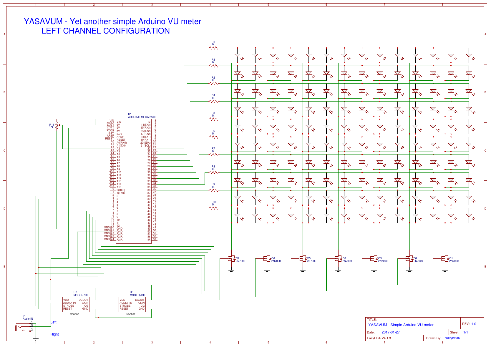
Schematic
Thanks a lot to YouTube user Wilson Carvajal for creating this schematic depicting the left half of the display as well as the Arduino and the MSGEQ7s. For the right half, simply connect another 10 pins to the Arduino, one for each row. The seven additional MOSFETs can be connected to the same pins that already drive the MOSFETs for the left half.
Licensing
YASAVUM is released under the Creative Commons Attribution Share-Alike license.